
9 Waves, Electromagnetic Radiation, and Sound

Figure 9.1 Waves in the ocean behave similarly to all other types of waves. (credit: Steve Jurveston, Flickr)
What do we mean when we say something is a wave? The most intuitive and easiest wave to imagine is the familiar water wave. More precisely, a wave is a disturbance that propagates, or moves from the place it was created. For water waves, the disturbance is on the surface of the water, perhaps created by a rock thrown into a pond or by a swimmer splashing the surface repeatedly. For sound waves, the disturbance is a change in air pressure, perhaps created by the oscillating cone inside a speaker. For earthquakes, there are several types of disturbances, including disturbance of Earth’s surface and pressure disturbances under the surface. Even radio waves are most easily understood using an analogy with water waves. Visualizing water waves is useful because there is more to it than just a mental image. Water waves exhibit characteristics common to all waves, such as amplitude, period, frequency and energy. All wave characteristics can be described by a small set of underlying principles.
The simplest waves repeat themselves for several cycles and are associated with simple harmonic motion. Let us start by considering the simplified water wave in Figure 9.2. The wave is an up and down disturbance of the water surface. It causes a seagull to move up and down in simple harmonic motion as the wave crests and troughs (peaks and valleys) pass under the bird. The time for one complete up and down motion is the wave’s period T.
The wave’s frequency is f = 1/T. The wave itself moves to the right in the figure. This movement of the wave is actually the disturbance moving to the right, not the water itself (or the bird would move to the right). We define wave velocity vw to be the speed at which the disturbance moves. Wave velocity is sometimes also called the propagation velocity or propagation speed, because the disturbance propagates from one location to another.
MISCONCEPTION ALERT
Many people think that water waves push water from one direction to another. In fact, the particles of water tend to stay in one location, save for moving up and down due to the energy in the wave. The energy moves forward through the water, but the water stays in one place. If you feel yourself pushed in an ocean, what you feel is the energy of the wave, not a rush of water.
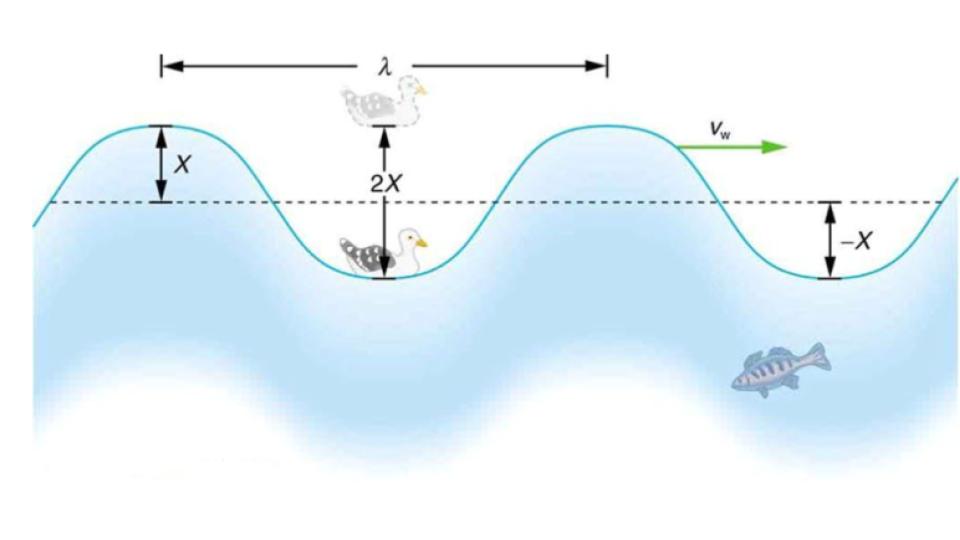 Figure 9.2 An idealized ocean wave passes under a sea gull that bobs up and down in simple harmonic motion. The wave has a wavelength λ, which is the distance between adjacent identical parts of the wave. The up and down disturbance of the surface propagates parallel to the surface at a speed vw. The water wave in the figure also has a length associated with it, called its wavelength λ, the distance between adjacent identical parts of a wave. λ is the distance parallel to the direction of propagation.) The speed of propagation vw is the distance the wave travels in a given time, which is one wavelength in the time of one period. In equation form, that is vw = λ/T or vw = fλ since f (frequency) = 1/T (period). This fundamental relationship holds for all types of waves. For water waves, vw is the speed of a surface wave; for sound, vw is the speed of sound; and for visible light, vw is the speed of light, for example.
TAKE-HOME EXPERIMENT: WAVES IN A BOWL
Fill a large bowl or basin with water and wait for the water to settle so there are no ripples. Gently drop a cork into the middle of the bowl. Estimate the wavelength and period of oscillation of the water wave that propagates away from the cork. Remove the cork from the bowl and wait for the water to settle again. Gently drop the cork at a height that is different from the first drop. Does the wavelength depend upon how high above the water the cork is dropped?
EXAMPLE 9.1 CALCULATE THE VELOCITY OF WAVE PROPAGATION: GULL IN THE OCEAN
Calculate the wave velocity of the ocean wave in Figure 9.2 if the distance between wave crests is 10.0 m and the time for a seagull to bob up and down is 5.00 s.
Strategy
We are asked to find vw. The given information tells us that λ = 10.0m and T = 5.00s. Therefore, we can use vw = λ/T to find the wave velocity.
Solution
- Enter the known values into vw = λ/T
vw = 10.0 m/5.00 s = 2.00 m
Discussion
This slow speed seems reasonable for an ocean wave. Note that the wave moves to the right in the figure at this speed, not the varying speed at which the seagull moves up and down.
Figure 9.3 shows how the various types of electromagnetic waves are categorized according to their wavelengths and frequencies—that is, it shows the electromagnetic spectrum. Many of the characteristics of the various types of electromagnetic waves are related to their frequencies and wavelengths, as we shall see.
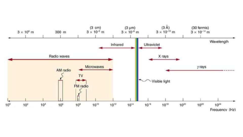
Figure 9.3 The electromagnetic spectrum, showing the major categories of electromagnetic waves. The range of frequencies and wavelengths is remarkable. The dividing line between some categories is distinct, whereas other categories overlap.
ELECTROMAGNETIC SPECTRUM: RULES OF THUMB
Three rules that apply to electromagnetic waves in general are as follows:
- High-frequency electromagnetic waves are more energetic and are more able to penetrate than low-frequency waves.
- High-frequency electromagnetic waves can carry more information per unit time than low-frequency waves.
- The shorter the wavelength of any electromagnetic wave probing a material, the smaller the detail it is possible to resolve.
Note that there are exceptions to these rules of thumb.
Transmission, Reflection, and Absorption
What happens when an electromagnetic wave impinges on a material? If the material is transparent to the particular frequency, then the wave can largely be transmitted. If the material is opaque to the frequency, then the wave can be totally reflected. The wave can also be absorbed by the material, indicating that there is some interaction between the wave and the material, such as the thermal agitation of molecules.
Of course it is possible to have partial transmission, reflection, and absorption. We normally associate these properties with visible light, but they do apply to all electromagnetic waves. What is not obvious is that something that is transparent to light may be opaque at other frequencies. For example, ordinary glass is transparent to visible light but largely opaque to ultraviolet radiation. Human skin is opaque to visible light—we cannot see through people—but transparent to X-rays.
Radio and TV Waves
The broad category of radio waves is defined to contain any electromagnetic wave produced by currents in wires and circuits. Its name derives from their most common use as a carrier of audio information (i.e., radio). The name is applied to electromagnetic waves of similar frequencies regardless of source. Radio waves from outer space, for example, do not come from alien radio stations. They are created by many astronomical phenomena, and their study has revealed much about nature on the largest scales.
There are many uses for radio waves, and so the category is divided into many subcategories, including microwaves and those electromagnetic waves used for AM and FM radio, cellular telephones, and TV.
The lowest commonly encountered radio frequencies are produced by high-voltage AC power transmission lines at frequencies of 50 or 60 Hz. (See Figure 9.4.) These extremely long wavelength electromagnetic waves (about 6000 km!) are one means of energy loss in long-distance power transmission.
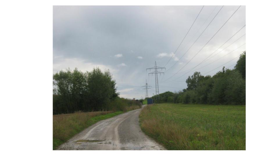
Figure 9.4 This high-voltage traction power line running to Eutingen Railway Substation in Germany radiates electromagnetic waves with very long wavelengths. (credit: Zonk43, Wikimedia Commons)
There is an ongoing controversy regarding potential health hazards associated with exposure to these electromagnetic fields. Some people suspect that living near such transmission lines may cause a variety of illnesses, including cancer. But demographic data are either inconclusive or simply do not support the hazard theory. Recent reports that have looked at many European and American epidemiological studies have found no increase in risk for cancer due to exposure to electromagnetic fields.
There are three ways in which light can travel from a source to another location. (See Figure 9.5.) It can come directly from the source through empty space, such as from the Sun to Earth. Or light can travel through various media, such as air and glass, to the person. Light can also arrive after being reflected, such as by a mirror. In all of these cases, light is modeled as traveling in straight lines called rays. Light may change direction when it encounters objects (such as a mirror) or in passing from one material to another (such as in passing from air to glass), but it then continues in a straight line or as a ray. It is acceptable to visualize light rays as laser rays (or even science fiction depictions of ray guns).
Ray
The word “ray” comes from mathematics and here means a straight line that originates at some point.
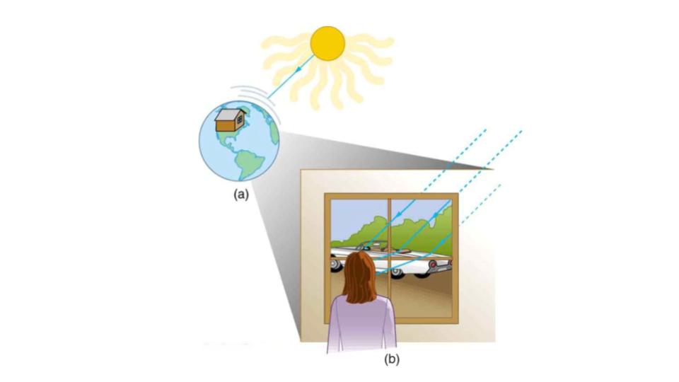
Figure 9.5 Three methods for light to travel from a source to another location. (a) Light reaches the upper atmosphere of Earth traveling through empty space directly from the source. (b) Light can reach a person in one of two ways. It can travel through media like air and glass. It can also reflect from an object like a mirror. In the situations shown here, light interacts with objects large enough that it travels in straight lines, like a ray.
Experiments, as well as our own experiences, show that when light interacts with objects several times as large as its wavelength, it travels in straight lines and acts like a ray. Its wave characteristics are not pronounced in such situations. Since the wavelength of light is less than a micron (a thousandth of a millimeter), it acts like a ray in the many common situations in which it encounters objects larger than a micron. For example, when light encounters anything we can observe with unaided eyes, such as a mirror, it acts like a ray, with only subtle wave characteristics. We will concentrate on the ray characteristics.
Since light moves in straight lines, changing directions when it interacts with materials, it is described by geometry and simple trigonometry. This part of optics, where the ray aspect of light dominates, is therefore called geometric optics. There are two laws that govern how light changes direction when it interacts with matter. These are the law of reflection, for situations in which light bounces off matter, and the law of refraction, for situations in which light passes through matter.
Geometric Optics
The part of optics dealing with the ray aspect of light is called geometric optics.
Whenever we look into a mirror, or squint at sunlight glinting from a lake, we are seeing a reflection. When you look at this page, too, you are seeing light reflected from it. Large telescopes use reflection to form an image of stars and other astronomical objects.
The law of reflection is illustrated in Figure 9.6, which also shows how the angles are measured relative to the perpendicular to the surface at the point where the light ray strikes. We expect to see reflections from smooth surfaces, but Figure 9.7 illustrates how a rough surface reflects light. Since the light strikes different parts of the surface at different angles, it is reflected in many different directions, or diffused. Diffused light is what allows us to see a sheet of paper from any angle, as illustrated in Figure 9.8. Many objects, such as people, clothing, leaves, and walls, have rough surfaces and can be seen from all sides. A mirror, on the other hand, has a smooth surface (compared with the wavelength of light) and reflects light at specific angles, as illustrated in Figure 9.9. When the moon reflects from a lake, as shown in Figure 9.10, a combination of these effects takes place.
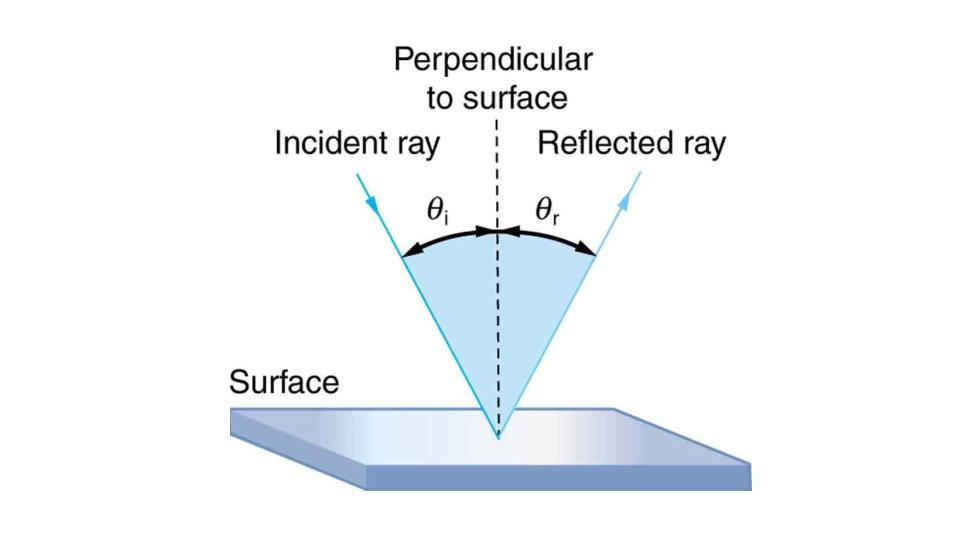
Figure 9.6 The law of reflection states that the angle of reflection equals the angle of incidence— θr = θi. The angles are measured relative to the perpendicular to the surface at the point where the ray strikes the surface.
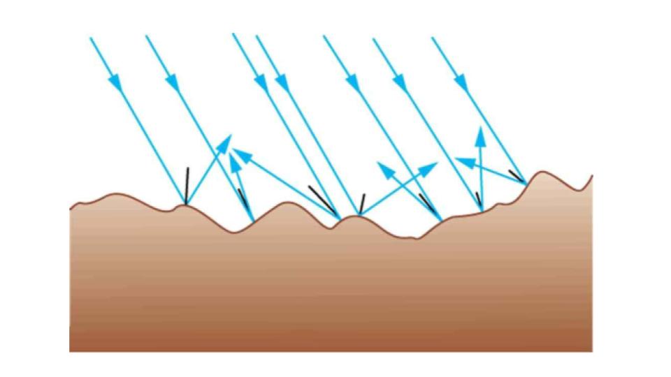
Figure 9.7 Light is diffused when it reflects from a rough surface. Here many parallel rays are incident, but they are reflected at many different angles since the surface is rough.
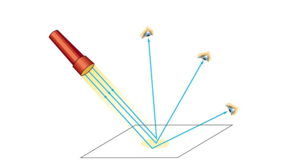
Figure 9.8 When a sheet of paper is illuminated with many parallel incident rays, it can be seen at many different angles, because its surface is rough and diffuses the light.
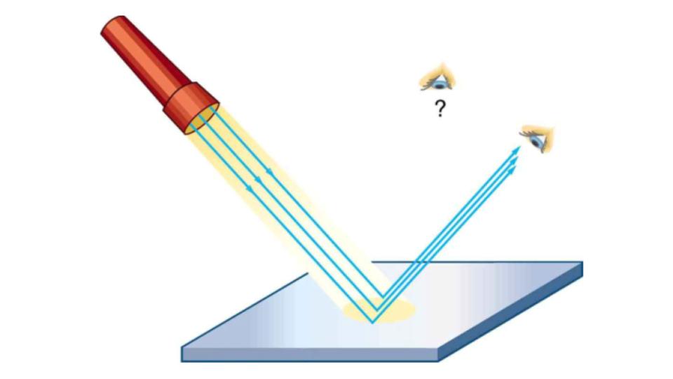
Figure 9.9 A mirror illuminated by many parallel rays reflects them in only one direction, since its surface is very smooth. Only the observer at a particular angle will see the reflected light.

Figure 9.10 Moonlight is spread out when it is reflected by the lake, since the surface is shiny but uneven. (credit: Diego Torres Silvestre, Flickr)
The law of reflection is very simple: The angle of reflection (θr) equals the angle of incidence (θi).
REFRACTION
The changing of a light ray’s direction (loosely called bending) when it passes through variations in matter is called refraction. Refraction is responsible for a tremendous range of optical phenomena, from the action of lenses to voice transmission through optical fibers.
SPEED OF LIGHT
The speed of light (c) not only affects refraction, it is one of the central concepts of Einstein’s theory of relativity. As the accuracy of the measurements of the speed of light were improved, c was found not to depend on the velocity of the source or the observer. However, the speed of light does vary in a precise manner with the material it traverses.
It is easy to notice some odd things when looking into a fish tank. For example, you may see the same fish appearing to be in two different places. (See Figure 9.11.) This is because light coming from the fish to us changes direction when it leaves the tank, and in this case, it can travel two different paths to get to our eyes.
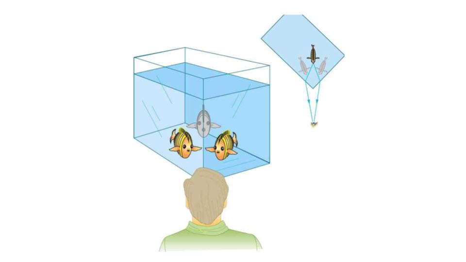
Figure 9.11 Looking at the fish tank as shown, we can see the same fish in two different locations, because light changes directions when it passes from water to air. In this case, the light can reach the observer by two different paths, and so the fish seems to be in two different places. This bending of light is called refraction and is responsible for many optical phenomena.
Bending Light
Explore bending of light between two media with different indices of refraction. See how changing from air to water to glass changes the bending angle. Play with prisms of different shapes and make rainbows.
LINK TO LEARNING: Use this interactive simulation by PhET to explore these two laws of light: Bending Light.
Geometric Optics
Lenses are found in a huge array of optical instruments, ranging from a simple magnifying glass to the eye to a camera’s zoom lens. In this section, we will use the law of refraction to explore the properties of lenses and how they form images.
The word lens derives from the Latin word for a lentil bean, the shape of which is similar to the convex lens in Figure 9.12. The convex lens shown has been shaped so that all light rays that enter it parallel to its axis cross one another at a single point on the opposite side of the lens. (The axis is defined to be a line normal, or perpendicular, to the lens at its center, as shown in Figure 9.12.) Such a lens is called a converging (or convex) lens for the converging effect it has on light rays. An expanded view of the path of one ray through the lens is shown, to illustrate how the ray changes direction both as it enters and as it leaves the lens. Since the index of refraction of the lens is greater than that of air, the ray moves towards the perpendicular as it enters and away from the perpendicular as it leaves. (This is in accordance with the law of refraction.) Due to the lens’s shape, light is thus bent toward the axis at both surfaces. The point at which the rays cross is defined to be the focal point F of the lens. The distance from the center of the lens to its focal point is defined to be the focal length f of the lens. Figure 9.13 shows how a converging lens, such as that in a magnifying glass, can converge the nearly parallel light rays from the sun to a small spot.
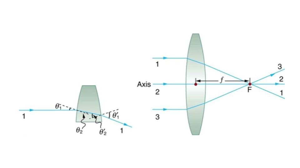
Figure 9.12 Rays of light entering a converging lens parallel to its axis converge at its focal point F. (Ray 2 lies on the axis of the lens.) The distance from the center of the lens to the focal point is the lens’s focal length f. An expanded view of the path taken by ray 1 shows the perpendiculars and the angles of incidence and refraction at both surfaces.
CONVERGING OR CONVEX LENS
The lens in which light rays that enter it parallel to its axis cross one another at a single point on the opposite side with a converging effect is called converging lens.
FOCAL POINT (F)
The point at which the light rays cross is called the focal point F of the lens.
FOCAL LENGTH (f)
The distance from the center of the lens to its focal point is called focal length f.
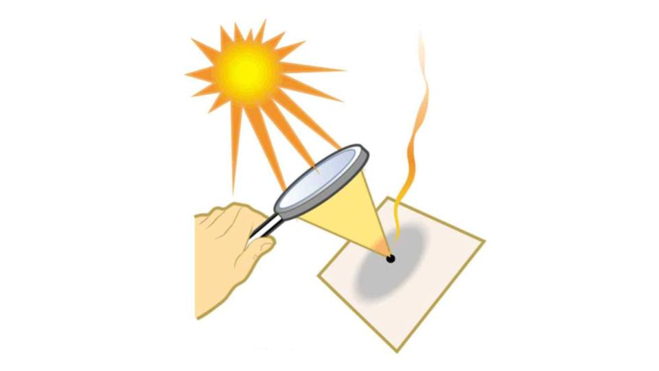
Figure 9.13 Sunlight focused by a converging magnifying glass can burn paper. Light rays from the sun are nearly parallel and cross at the focal point of the lens. The more powerful the lens, the closer to the lens the rays will cross.
The greater effect a lens has on light rays, the more powerful it is said to be. For example, a powerful converging lens will focus parallel light rays closer to itself and will have a smaller focal length than a weak lens. The light will also focus into a smaller and more intense spot for a more powerful lens.
DIVERGING LENS
A lens that causes the light rays to bend away from its axis is called a diverging lens.
As noted in the initial discussion of the law of refraction, the paths of light rays are exactly reversible. This means that the direction of the arrows could be reversed for all of the rays in Figure 9.12. For example, if a point light source is placed at the focal point of a convex lens, as shown in Figure 9.14, parallel light rays emerge from the other side.
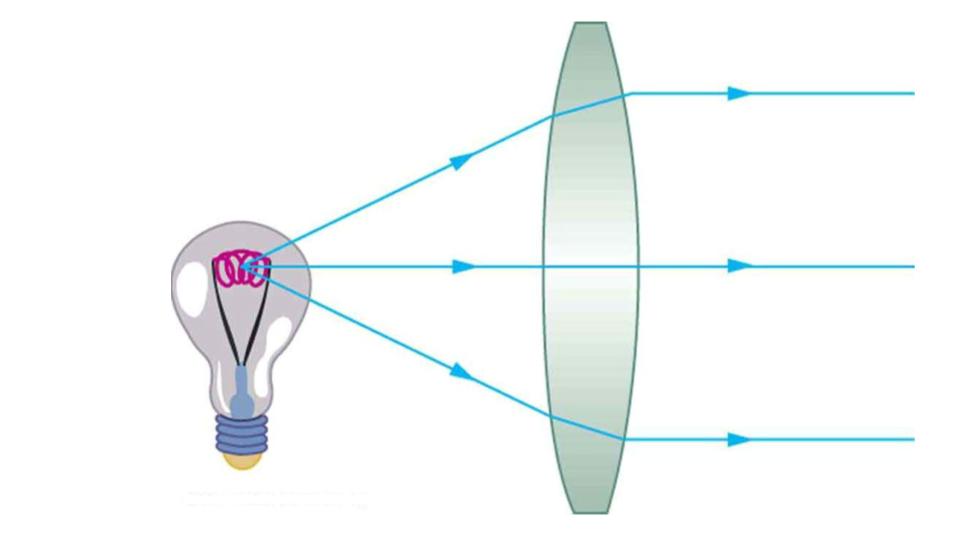
Figure 9.14 A small light source, like a light bulb filament, placed at the focal point of a convex lens, results in parallel rays of light emerging from the other side. The paths are exactly the reverse of those shown in Figure 9.12. This technique is used in lighthouses and sometimes in traffic lights to produce a directional beam of light from a source that emits light in all directions.
Ray Tracing and Thin Lenses
Ray tracing is the technique of determining or following (tracing) the paths that light rays take. For rays passing through matter, the law of refraction is used to trace the paths. Here we use ray tracing to help us understand the action of lenses in situations ranging from forming images on film to magnifying small print to correcting nearsightedness. While ray tracing for complicated lenses, such as those found in sophisticated cameras, may require computer techniques, there is a set of simple rules for tracing rays through thin lenses. A thin lens is defined to be one whose thickness allows rays to refract, as illustrated in Figure 9.12, but does not allow properties such as dispersion and aberrations. An ideal thin lens has two refracting surfaces but the lens is thin enough to assume that light rays bend only once. A thin symmetrical lens has two focal points, one on either side and both at the same distance from the lens. (See Figure 9.15.) Another important characteristic of a thin lens is that light rays through its center are deflected by a negligible amount, as seen in Figure 9.16.
THIN LENS
A thin lens is defined to be one whose thickness allows rays to refract but does not allow properties such as dispersion and aberrations.
TAKE-HOME EXPERIMENT: A VISIT TO THE OPTICIAN
Look through your eyeglasses (or those of a friend) backward and forward and comment on whether they act like thin lenses.
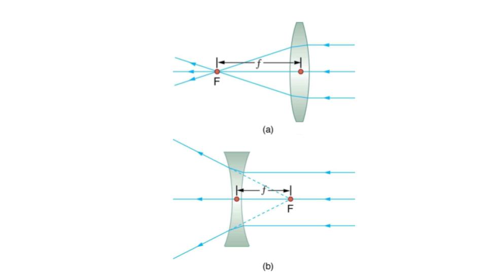
Figure 9.15 Thin lenses have the same focal length on either side. (a) Parallel light rays entering a converging lens from the right cross at its focal point on the left. (b) Parallel light rays entering a diverging lens from the right seem to come from the focal point on the right.
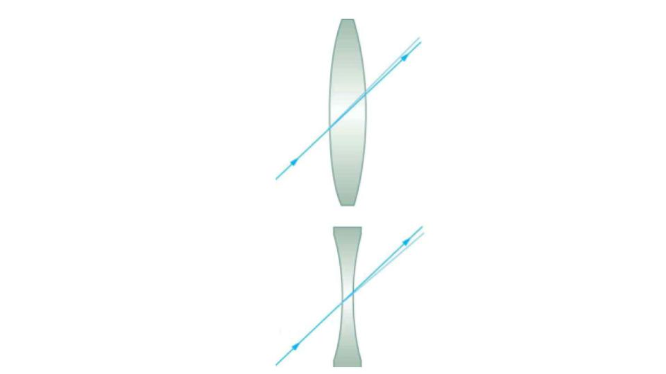
Figure 9.16 The light ray through the center of a thin lens is deflected by a negligible amount and is assumed to emerge parallel to its original path (shown as a shaded line).
Using paper, pencil, and a straight edge, ray tracing can accurately describe the operation of a lens.
Image Formation by Thin Lenses
In some circumstances, a lens forms an obvious image, such as when a movie projector casts an image onto a screen. In other cases, the image is less obvious. Where, for example, is the image formed by eyeglasses? We will use ray tracing for thin lenses to illustrate how they form images, and we will develop equations to describe the image formation quantitatively.
Consider an object some distance away from a converging lens, as shown in Figure 9.17. To find the location and size of the image formed, we trace the paths of selected light rays originating from one point on the object, in this case the top of the person’s head. The figure shows three rays from the top of the object that can be traced using the ray tracing rules given above. (Rays leave this point going in many directions, but we concentrate on only a few with paths that are easy to trace.) The first ray is one that enters the lens parallel to its axis and passes through the focal point on the other side (rule 1). The second ray passes through the center of the lens without changing direction (rule 3). The third ray passes through the nearer focal point on its way into the lens and leaves the lens parallel to its axis (rule 4). The three rays cross at the same point on the other side of the lens. The image of the top of the person’s head is located at this point. All rays that come from the same point on the top of the person’s head are refracted in such a way as to cross at the point shown. Rays from another point on the object, such as her belt buckle, will also cross at another common point, forming a complete image, as shown. Although three rays are traced in Figure 9.17, only two are necessary to locate the image. It is best to trace rays for which there are simple ray tracing rules. Before applying ray tracing to other situations, let us consider the example shown in Figure 9.17 in more detail.
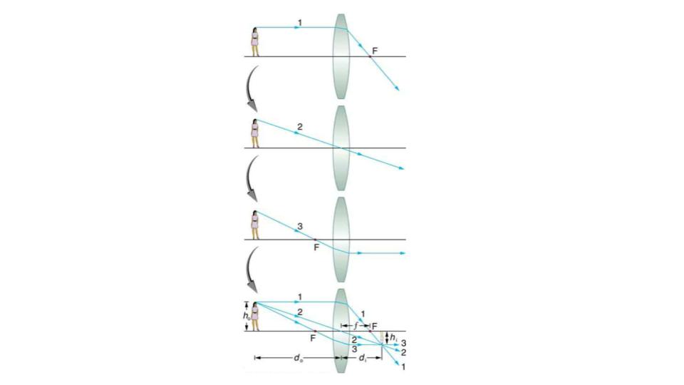
Figure 9.17 Ray tracing is used to locate the image formed by a lens. Rays originating from the same point on the object are traced—the three chosen rays each follow one of the rules for ray tracing, so that their paths are easy to determine. The image is located at the point where the rays cross. In this case, a real image—one that can be projected on a screen—is formed.
The image formed in Figure 9.17 is a real image, meaning that it can be projected. That is, light rays from one point on the object actually cross at the location of the image and can be projected onto a screen, a piece of film, or the retina of an eye, for example. Figure 9.18 shows how such an image would be projected onto film by a camera lens. This figure also shows how a real image is projected onto the retina by the lens of an eye. Note that the image is there whether it is projected onto a screen or not.
REAL IMAGE
The image in which light rays from one point on the object actually cross at the location of the image and can be projected onto a screen, a piece of film, or the retina of an eye is called a real image.
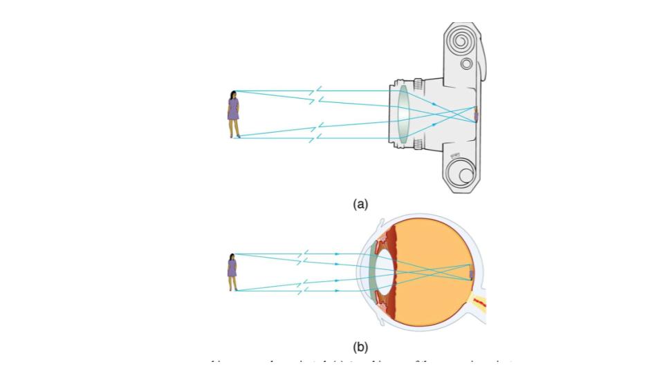
Figure 9.18 Real images can be projected. (a) A real image of the person is projected onto film. (b) The converging nature of the multiple surfaces that make up the eye result in the projection of a real image on the retina.
Real images, such as the one considered in the previous example, are formed by converging lenses whenever an object is farther from the lens than its focal length. This is true for movie projectors, cameras, and the eye.
A different type of image is formed when an object, such as a person’s face, is held close to a convex lens. The image is upright and larger than the object, as seen in Figure 9.19 (b), and so the lens is called a magnifier. If you slowly pull the magnifier away from the face, you will see that the magnification steadily increases until the image begins to blur. Pulling the magnifier even farther away produces an inverted image as seen in Figure 9.19 (a). The distance at which the image blurs, and beyond which it inverts, is the focal length of the lens. To use a convex lens as a magnifier, the object must be closer to the converging lens than its focal length.
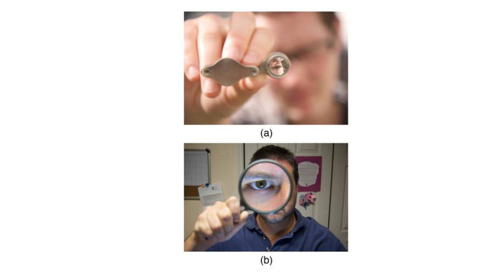
Figure 9.19 (a) When a converging lens is held farther away from the face than the lens’s focal length, an inverted image is formed. Note that the image is in focus but the face is not, because the image is much closer to the camera taking this photograph than the face. (credit: DaMongMan, Flickr) (b) A magnified image of a face is produced by placing it closer to the converging lens than its focal length. (credit: Casey Fleser, Flickr)
Figure 9.20 uses ray tracing to show how an image is formed when an object is held closer to a converging lens than its focal length. Rays coming from a common point on the object continue to diverge after passing through the lens, but all appear to originate from a point at the location of the image. The image is on the same side of the lens as the object and is farther away from the lens than the object. This image, like all case 2 images, cannot be projected and, hence, is called a virtual image. Light rays only appear to originate at a virtual image; they do not actually pass through that location in space. A screen placed at the location of a virtual image will receive only diffuse light from the object, not focused rays from the lens. Additionally, a screen placed on the opposite side of the lens will receive rays that are still diverging, and so no image will be projected on it. We can see the magnified image with our eyes, because the lens of the eye converges the rays into a real image projected on our retina. Finally, we note that a virtual image is upright and larger than the object, meaning that the magnification is positive and greater than 1.
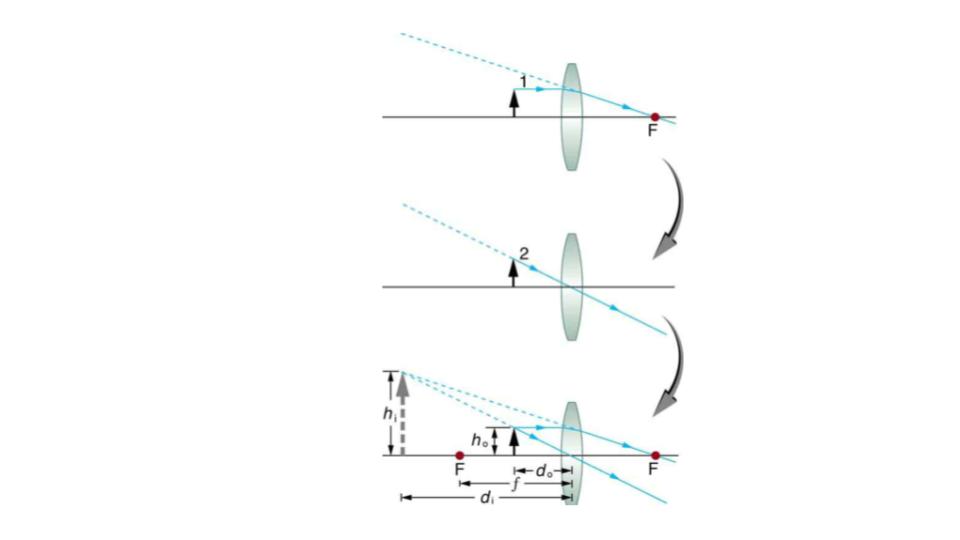
Figure 9.20 Ray tracing predicts the image location and size for an object held closer to a converging lens than its focal length. Ray 1 enters parallel to the axis and exits through the focal point on the opposite side, while ray 2 passes through the center of the lens without changing path. The two rays continue to diverge on the other side of the lens, but both appear to come from a common point, locating the upright, magnified, virtual image. This is a case 2 image.
Virtual Image
An image that is on the same side of the lens as the object and cannot be projected on a screen is called a virtual image.
A third type of image is formed by a diverging or concave lens. Try looking through eyeglasses meant to correct nearsightedness. (See Figure 9.21.) You will see an image that is upright but smaller than the object. This means that the magnification is positive but less than 1. The ray diagram in Figure 9.22 shows that the image is on the same side of the lens as the object and, hence, cannot be projected—it is a virtual image. Note that the image is closer to the lens than the object. This is a case 3 image, formed for any object by a negative focal length or diverging lens.
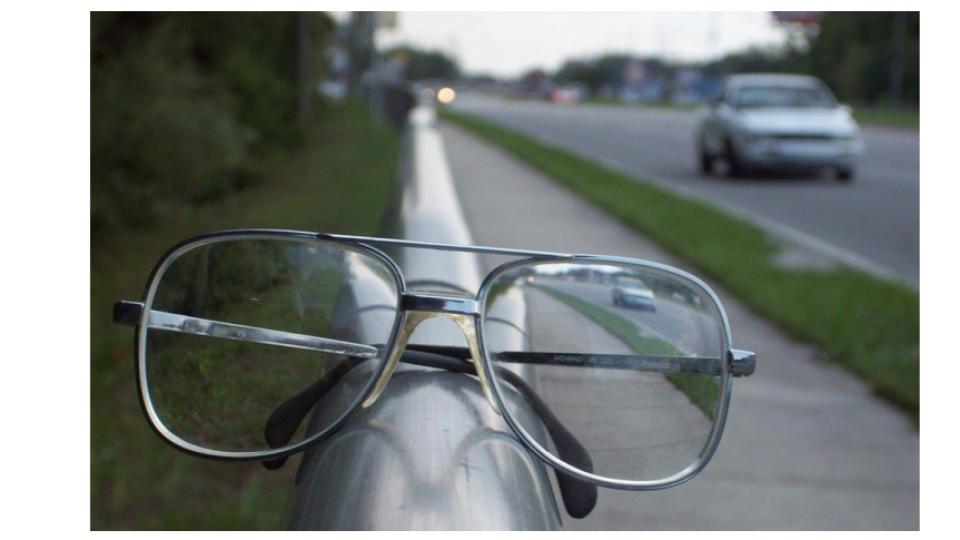
Figure 9.21 A car viewed through a concave or diverging lens looks upright. This is a case 3 image. (credit: Daniel Oines, Flickr)
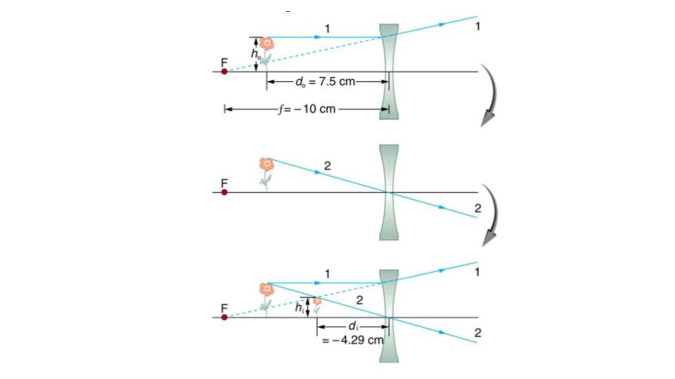
Figure 9.22 Ray tracing predicts the image location and size for a concave or diverging lens. Ray 1 enters parallel to the axis and is bent so that it appears to originate from the focal point. Ray 2 passes through the center of the lens without changing path. The two rays appear to come from a common point, locating the upright image.
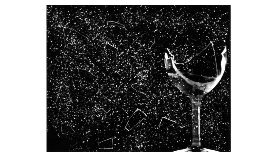
Figure 9.23 This glass has been shattered by a high-intensity sound wave of the same frequency as the resonant frequency of the glass. While the sound is not visible, the effects of the sound prove its existence. (credit: ||read||, Flickr)
Sound
Sound can be used as a familiar illustration of waves. Because hearing is one of our most important senses, it is interesting to see how the physical properties of sound correspond to our perceptions of it. Hearing is the perception of sound, just as vision is the perception of visible light. But sound has important applications beyond hearing. Ultrasound, for example, is not heard but can be employed to form medical images and is also used in treatment.
The physical phenomenon of sound is defined to be a disturbance of matter that is transmitted from its source outward. Sound is a wave. On the atomic scale, it is a disturbance of atoms that is far more ordered than their thermal motions. In many instances, sound is a periodic wave, and the atoms undergo simple harmonic motion.
A vibrating string produces a sound wave as illustrated in Figure 9.24, Figure 9.25, and Figure 9.26. As the string oscillates back and forth, it transfers energy to the air, mostly as thermal energy created by turbulence. But a small part of the string’s energy goes into compressing and expanding the surrounding air, creating slightly higher and lower local pressures. These compressions (high pressure regions) and rarefactions (low pressure regions) move out as longitudinal pressure waves having the same frequency as the string—they are the disturbance that is a sound wave. (Sound waves in air and most fluids are longitudinal, because fluids have almost no shear strength. In solids, sound waves can be both transverse and longitudinal.) Figure 9.26 shows a graph of gauge pressure versus distance from the vibrating string.
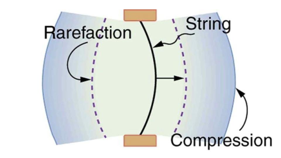
Figure 9.24 A vibrating string moving to the right compresses the air in front of it and expands the air behind it.
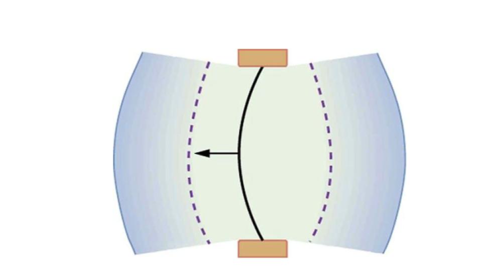
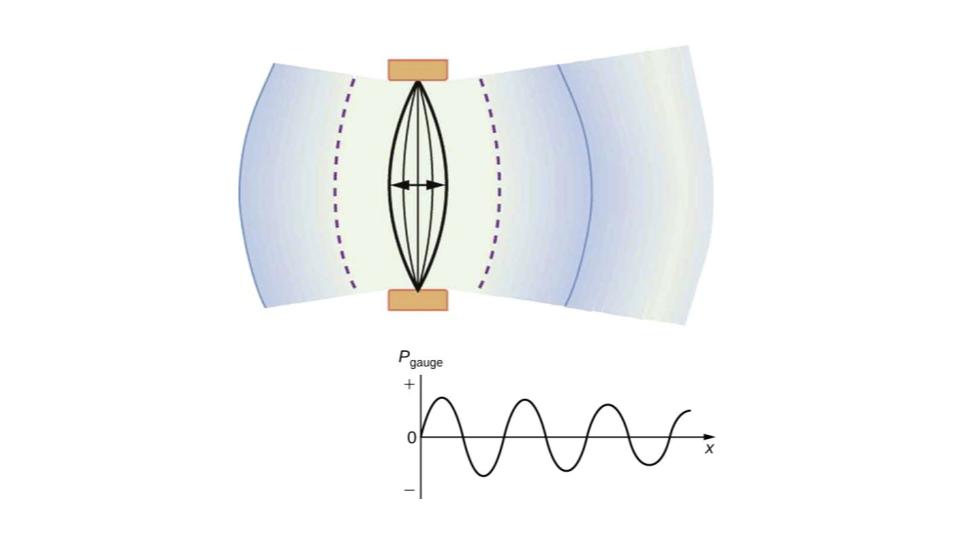
Figure 9.26 After many vibrations, there are a series of compressions and rarefactions moving out from the string as a sound wave. The graph shows gauge pressure versus distance from the source. Pressures vary only slightly from atmospheric for ordinary sounds. Note that sound waves consist of these changes in density or pressure of a medium and thus are *not* electromagnetic radiation.
