
Module 2: Using the Petrographic Microscope
2.4 Parts of the Petrographic Microscope
Elizabeth A. Johnson; Juhong Christie Liu; and Mark Peale
In this section, we explore the parts of the petrographic or polarizing light microscope. This section is appropriate for students who have no prior experience with using microscopes.
This is also a good review for those who could use a refresher on the anatomy of a microscope.
Learning Objectives
Students will be able to:
- Identify and describe the purpose of each part of a petrographic microscope.
- Describe the typical pathway of light through a petrographic microscope.
Prior Knowledge and Skills
Overview of the Microscope
What does a microscope look like? Although all petrographic microscopes have common parts and functions, there are many brands of microscope, each of which may look different. If petrographic microscopes are maintained and handled carefully, they can last for literally generations of students. The microscopes in your classroom or the laboratory could be new, a few years old, or decades old, and have different design aspects from younger or older microscopes.
There are research-grade microscopes that have better-quality optics and more accessories, in contrast to student-grade microscopes that may have fewer features but are built for typical analyses and heavier use. Let’s look at three examples of petrographic microscopes:
Guided Inquiry
If all microscopes look somewhat different from each other, are the examples shown here relevant to your microscope? They should be! It turns out that even though various microscopes might look different at first glance, because all petrographic microscopes will have common functions, the overall design and structure of microscopes is similar. Even if the analyzer on your microscope looks different from mine, they should be in a similar location on both microscopes and should function in a similar way.
Let’s explore the general structure of a petrographic microscope. Click on the + signs to show the part names. In the sections below, we will investigate each part in detail.
Fig. 2.4.2. general structure of a petrographic microscope
The Illuminator
The illuminator is a steady light source that is located in the base of the microscope. It is used for transmitted light microscopy.
The switch to turn on the illuminator is typically located at the rear or on the side of the base of the microscope. When the illuminator is ON, light will be visible through the base in the microscope. The following video clips show examples of turning on the illuminator for different microscopes:
Fig. 2.4.3. Turning on the illuminator.
If you are lucky enough to have a microscope that has both transmitted and reflected light capabilities, then the microscope will also have a light source near the top rear which can illuminate the sample from above.
Guided Inquiry
The Condenser and Substage Assembly
The parts of the microscope that are located above the base but below the stage are called the substage assembly. The substage assembly includes the condenser, the lower polarizer, light filters, and diaphragms.
Figure 2.4.5. Interactive video showing typical adjustments that can be made on the substage assembly.
CondensEr
The condenser consists of two or more lenses that focus the illuminator light onto the sample placed on the stage, and one or more apertures to control illumination (see below). The condenser should be adjusted each time the objective lens is changed to maximize the quality of the image.
Lower Polarizer
The first polarizer is located below the condenser and is shown in the interactive video above (Figure 2.4.5). Please see the separate section below on polarizers for more information.
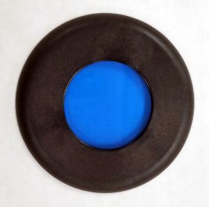
Light filter
Halogen lights used in microscopes typically give off a yellowish light, so a blue filter is often added to compensate for the yellow color of the light, providing a truer white light to pass through the sample.
Diaphragm or Aperture
A diaphragm or aperture cuts down the amount of light that reaches the sample by restricting the area that light can pass through. There are often multiple apertures on a microscope (Figure 2.4.5), including an aperture as part of the condenser assembly, as well as a field diaphragm that controls the size of the area which is illuminated on a sample.
Figure 2.4.7 shows the view through the microscope as the substage field diaphragm is opened and closed.
The Stage
Rotating Stage, Goniometer, and Vernier Scale
The stage is the platform upon which the thin section is placed. The thin section spans a hole in the stage which lets light from the illuminator pass through the sample. One special feature of polarizing light microscopes used for petrography, in contrast to many other types of microscopes, is the rotating stage.
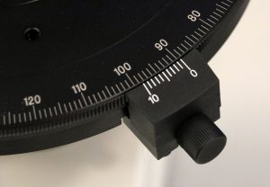
Figure 2.4.8.B.The rotating stage in action, showing how the angle of orientation can be measured using the goniometer and venier. The rotating stage can be locked with the knob on the vernier.
The rotating stage has degrees marked on it: 360 degrees around the circular stage, in units of 1 degree. The angle of rotation can be measured to the nearest tenth of a degree by using the markings on the vernier scale. The rotating stage can therefore be used as a goniometer, or an instrument that measures rotational angle.
The vernier scale is a clever way of taking an accurate measurement reading between two markings on a linear scale by using mechanical interpolation. Figure 2.4.9 shows the distance reading recorded as the yellow vernier scale slides alongside the ruler scale. The distance starts at exactly 5.0 mm, when “0” on the vernier exactly aligns with “5” on the ruler. To determine a distance greater than 5.0 mm (but less than 6.0 mm), one identifies the line on the vernier which aligns with one of the lines on the main ruler. For example, when line “1” on the vernier aligns perfectly with one of the lines on the ruler, then the distance is 5.1 mm.
Guided Inquiry
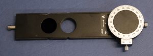
Mechanical Stage
The mechanical stage is an accessory which can be attached to the top of the rotating stage. Rather than a rotating motion, it allows motion along the x-axis (left-right) and y-axis (top-bottom). In Figure 2.4.10, the gold knob at the top controls motion in the x direction, and the gold knob on the right controls the y direction motion. The pincer-like arms (bottom left) wrap around the thin section and hold it in place.
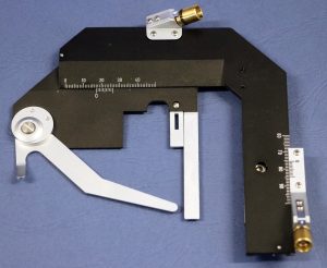
The mechanical stage is not necessary for the optical mineralogy procedures discussed in this chapter. However, it is useful for point counting, in which the petrographer stops at several hundred points along an x-y grid on a thin section and identifies the mineral at each point. This technique is used to determine the modal abundance of minerals in the thin section, and is used to determine the name and composition of rocks.
The Focus
Most polarizing light microscopes have two focusing knobs on each side of the microscope. The coarse focus is used to rapidly change the level of the stage and sample, and the fine focus knob is used to gently bring a sample into complete focus.
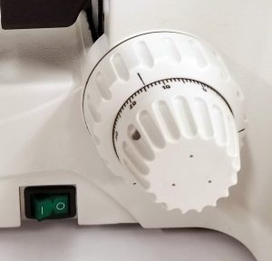
Care is required when using the coarse focus knob! Because it changes the level of the stage rapidly, it may be easier to run the sample into an objective and damage the thin section and possibly the objective also.
The Objectives and Revolving Nosepiece
Objectives are the main (but usually not the only) magnification mechanism in the microscope. Magnifications typically range from about 4x-64x, although objectives as low as 2.5x and as high as 200x are available. Because most polarizing light microscopes are compound microscopes containing more than one lens, the total magnification can be much higher (see the oculars section below).
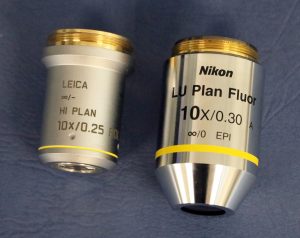
Objectives are attached to the revolving nosepiece (see Figure 2.4.2). They can be centered using centering screws on either side of the objective. To change objectives, one should grasp the nosepiece, and not the objective itself.
The Polarizers
The polarizers in petrographic microscopes are plane (linearly) polarized. See section 2.3 for more information about how polarizers work. There is a polarizer in the substage assembly, and a second polarizer called the analyzer between the objectives and the Bertrand lens.
Typically the lower polarizer and analyzer are oriented at 90 degrees to each other, and oriented N-S and E-W relative to the base of the microscope. Polarization directions are marked either on the base of the microscope, or on the polarizers themselves. In some microscopes, the analyzer and the lower polarizer can be rotated (Figure 2.4.13) for custom measurements. This is not necessary for standard petrographic analyses.
The (Amici-) Bertrand Lens
The Amici-Bertrand lens (or simply the Bertrand lens) changes the plane of focus so that the viewer can observe interference figures (a technique discussed in section 2.8).
Figure 2.4.14. The Bertrand lens being inserted and removed, as viewed with the ocular removed.
The Eyepieces or Oculars
Polarizing light microscopes have eyepieces or oculars through which the user can observe the sample. Most modern microscopes are binocular and have two eyepieces which can be adjusted relative to each other to comfortably fit the user’s eyes. Older models may have only one eyepiece (as in Figure 2.4.1), but are just as effective in making petrographic observations.
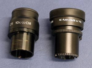
Most oculars contain magnifying lenses that are typically 10x magnification but can vary from model to model. The magnification should be marked on the eyepiece, and should be included in the total magnification of the microscope.
One ocular (typically the right one in a binocular microscope) will include crosshairs with a distance scale. This distance scale can be calibrated for each magnification, to determine the field of view (the diameter of the viewing circle) and the distance represented by each mark on the ocular scale (see Question 2.4.7 below).
Oculars have a focusing mechanism to adjust the focus to each individual eye. The top portion of the ocular (the part with writing as seen in Figure 2.4.15) can be rotated to adjust the focus. If the crosshairs look fuzzy, or one eye seems in focus but the other is not, try adjusting the ocular focus to help you see better,
Guided Inquiry
The total magnification of a compound microscope such as a polarizing light microscope is given by this formula:
Total magnification = magnification of the objective x magnification of the ocular.
For example, if the ocular has 10x magnification and I am using the 10x objective, the total magnification is 100x.
The Camera
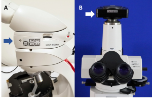
Some polarizing light microscopes have digital camera attachments, making it possible to directly photograph the field of view in the microscope. Some microscopes (Figure 2.4.16.A) have a camera embedded within the microscope, while for others the camera is attached to the microscope with its own viewing tube (Figure 2.4.16B). In microscopes with separate camera viewing tubes, the light must be adjusted to travel partially or completely to the camera. This is accomplished with a pull-out knob (seen to the right of the eyepieces in Figure 2.4.16B).
It is possible to obtain images from a microscope by aiming a smart phone camera down the ocular. However, these images will be circular in shape and may be distorted or partially out of focus. If available, the camera attached to the microscope will likely produce better-quality images.
The Accessory Plates
Figure 2.4.17 shows examples of accessory plates including a quartz wedge, a 530 nm plate, and a 1/4 λ plate. These can be inserted into the microscope (Figure 2.4.2) above the objectives. The accessory plates are used to conduct advanced optical tests such as optical sign determination.
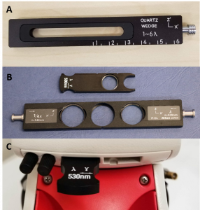
The quartz wedge is just that – a slab of quartz polished into a wedge that has a thicker side which grades into a thinner side. The 530 nm plate can also be called a gypsum plate or a 1λ plate, or be a slightly different wavelength (550 or 537 nm). The 1/4λ plate can also be called a mica plate, glimmer plate, or 147 nm.
Summary Questions
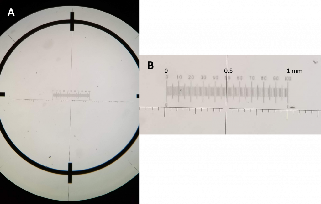
Question 2.4.7. Using Figure 2.4.18, determine the field of view (the diameter of the circular illuminated area). Note that the thick dark circle and hatch marks are part of the micrometer slide. The field of view includes the entire white area and is cut off on the right and left sides, but its edges can be viewed on the top and bottom of the photo.
Question 2.4.8. Using Figure 2.4.18 and the micrometer slide scale, determine the distance between each small tick mark on the unmarked ocular micrometer scale.
Figure 2.4.19. Two commonly used ways to change objective lenses. One of these methods is incorrect and should not be used!
Key Takeaways
- Although petrographic microscopes can look different from each other, since they all function in a similar manner, the parts should be located in similar positions from microscope to microscope.
- Understanding the function of each part of the microscope will help when making petrographic observations and measurements.
Key Terms
Accessory plate
(Amici-) Bertrand lens
Analyzer
Aperture
Base
Condenser
Condenser aperture diaphragm
Eyepiece or Ocular
Field diaphragm
Focus (coarse and fine)
Goniometer
Illumination intensity controller
Illuminator
Light Filter
Mechanical stage
Objective lens
Petrographic microscope
Polarizer
(Revolving) nosepiece
Rotating stage
Substage assembly
Substage centering screw
Vernier scale
Viewing tube
References
Wikipedia. Vernier scale. (Ret. 12/12/19) https://en.wikipedia.org/wiki/Vernier_scale
Media Attributions
- 2_4_6 Blue filter © Elizabeth A. Johnson is licensed under a CC BY (Attribution) license
- 2_4_8a Vernier on rotating stage © Elizabeth A. Johnson is licensed under a CC BY-SA (Attribution ShareAlike) license
- 2_4_9 Vernierscale © Lookang many thanks to Fu-Kwun Hwang and author of Easy Java Simulation = Francisco Esquembre is licensed under a CC BY-SA (Attribution ShareAlike) license
- 2_4_10 Mechanical Stage © Elizabeth A. Johnson and Mark Peale is licensed under a CC BY-SA (Attribution ShareAlike) license
- 2_4_11 Focus knobs © Elizabeth A. Johnson is licensed under a CC BY-SA (Attribution ShareAlike) license
- 2_4_12 Objective lenses
- 2_4_13 Polarizer © Elizabeth A. Johnson and Mark Peale is licensed under a CC BY-SA (Attribution ShareAlike) license
- 2_4_15 Eyepieces © Elizabeth A. Johnson is licensed under a CC BY-SA (Attribution ShareAlike) license
- 2_4_16 Cameras © Elizabeth A. Johnson and Mark Peale is licensed under a CC BY-SA (Attribution ShareAlike) license
- 2_4_17 Accessory Plates © Elizabeth A. Johnson and Mark Peale is licensed under a CC BY-SA (Attribution ShareAlike) license
- 2_4_18 Calibrating scale © Elizabeth A. Johnson is licensed under a CC BY-SA (Attribution ShareAlike) license
