
Module 2: Using the Petrographic Microscope
2.8 Interference Figures: Part 2
Elizabeth A. Johnson and Juhong Christie Liu
Biaxial Interference Figures
The following two videos explain how to obtain biaxial interference figures, how to determine optic sign for a biaxial mineral, and how to estimate a 2V angle.
Figure 2.8.10. Earth Optics Videos. Video 6: Biaxial Minerals. CC-BY license. https://youtu.be/pA_fJnbPRtg
Figure 2.8.11. Earth Optics Videos. Video 7: Biaxial Flash Figure. CC-BY license. https://youtu.be/qCkljJ1Isjw
Biaxial interference figure diagrams.
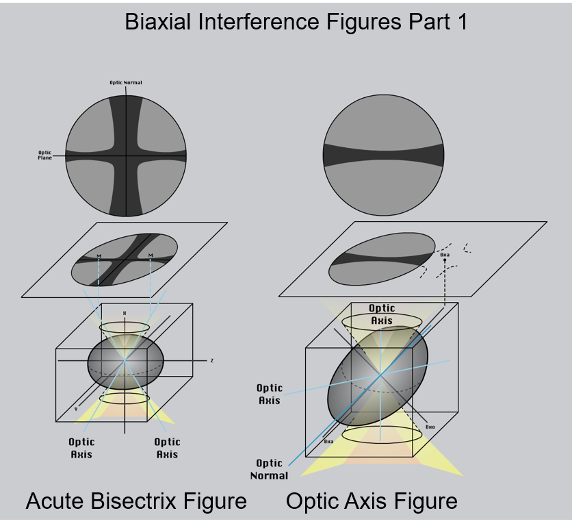
M= melatope; Bxa = acute bisectrix; Bxo = obtuse bisectrix.
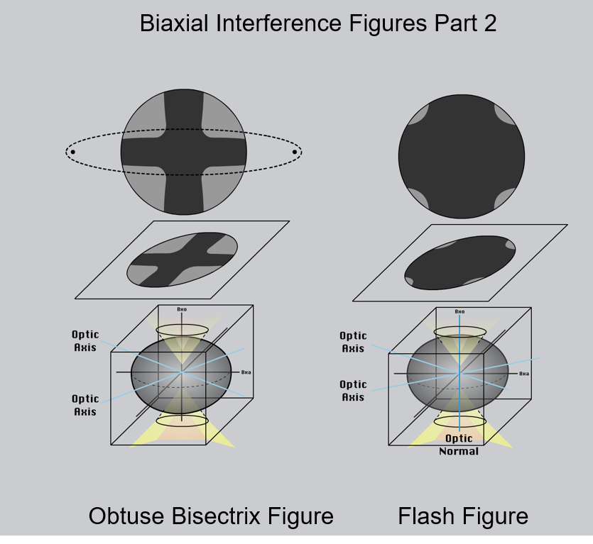
Bxa = acute bisectrix; Bxo = obtuse bisectrix.
Figure 2.8.13. An acute bisectrix optical interference figure obtained on albite.
Figure 2.8.14. An optical interference figure obtained on an augite crystal oriented parallel to the 001 crystallographic direction.
Figure 2.8.15. An optical flash figure obtained on an augite crystal.
Guided Inquiry
Interference Figures and Crystal Symmetry
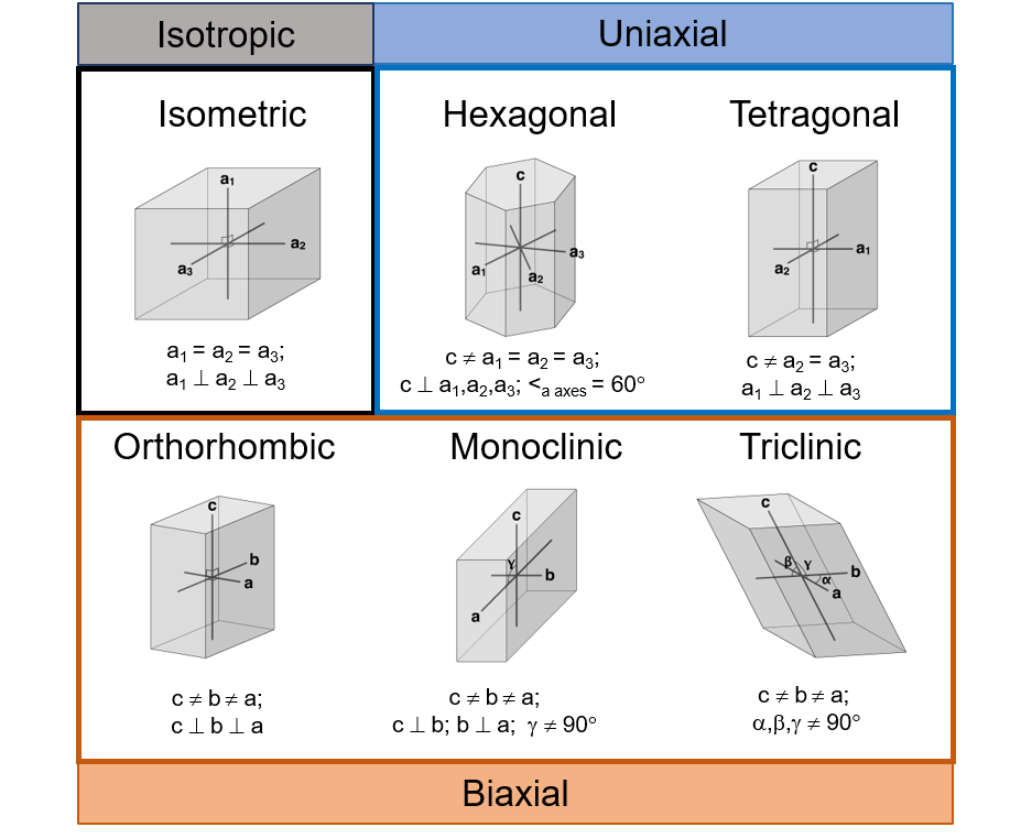
The types of interference figures that a mineral produces are related to the crystal symmetry of that mineral. The figure below summarizes the division of crystal symmetries into isotropic, uniaxial, and biaxial optical properties.
Guided Inquiry
Synthesis: Is it Uniaxial or Biaxial?
Figure 2.8.17. An interference figure obtained on a calcite crystal.
Figure 2.8.18. An interference figure obtained on a nepheline crystal.
Guided Inquiry
Media Attributions
- 2_8_10 Biaxial interference figs part 1 © Mark Peale and Elizabeth Johnson is licensed under a CC BY-NC-SA (Attribution NonCommercial ShareAlike) license
- 2_8_10 Biaxial interference figs part 2 © Mark Peale and Elizabeth Johnson is licensed under a CC BY-NC-SA (Attribution NonCommercial ShareAlike) license
- Crystal Symmetry and Optical Properties © Elizabeth Johnson and Mark Peale is licensed under a CC BY-NC-SA (Attribution NonCommercial ShareAlike) license
