Module 2: Using the Petrographic Microscope
2.6 Properties Under Plane Polarized Light
Elizabeth A. Johnson; Juhong Christie Liu; and Mark Peale
In this section, we explore properties that can be observed for minerals under plane polarized light, when only the lower polarizer is inserted into the polarizing light microscope.
Learning Objectives
In this section, students will learn to:
- Distinguish opaque minerals from transparent minerals.
- Identify the color(s) of minerals in plane polarized light.
- Identify and describe pleochroism.
- Determine if a mineral has low, medium, or high relief.
- Describe the relationship between refractive index and relief.
- Describe mineral form as euhedral, subhedral, or anhedral.
- Identify cleavage and fracture in minerals.
Overview of Properties in Plane Polarized Light
This video gives an overview of some of the important properties of minerals in plane polarized light. These properties are explored in more detail in the sections below.
Figure 2.6.1. Some techniques that use plane polarized light. Earth Optics Videos, Creative Commons Attribution License.
Opaque vs. Transparent Minerals
Transparent minerals transmit light, whereas opaque minerals block light from passing through them. Because most student microscopes only have an option to look at minerals under transmitted light, this means that all opaque minerals will appear dark in plane polarized light. Some very small opaque minerals, or minerals within a group that contains both opaque and transparent minerals (such as the spinel group) may let some light through and could appear to have some color.
Microscopes with the ability to view thin sections under both reflected and transmitted light do exist, and different opaque minerals will reflect light differently. This type of microscope is most commonly used for studying ore deposits or other rocks containing many opaque mineral species.
Guided Inquiry
Question 2.6.1. The two figures above show magnetite (Figure 2.6.2) and garnet (Figure 2.6.3) in both plane polarized light (PPL) and cross polarized light (XPL). Based upon the definition of opaque minerals, which of these are opaque? Why?
Color
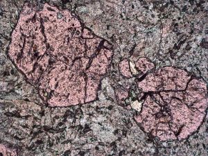
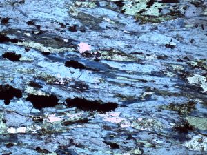
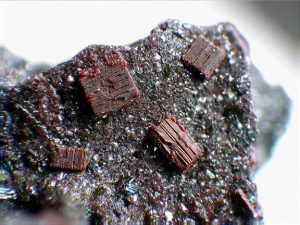
Some minerals that are darkly colored in hand sample will also appear to have color in thin section, even though the rock slices in thin sections are typically only 30 micrometers thick. Sometimes the color of a mineral in plane polarized light can aid in identification (see examples in the figures below) because it is characteristic for a specific mineral.
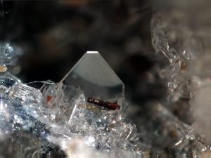
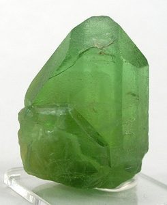
But, be cautious about relying too heavily on color as an identification tool! Minerals within a solid solution group can have very different color characteristics in hand sample (as shown in Figure 2.6.6) and under the microscope.
 |
 |
 |
Pleochroism
Pleochroism is when a mineral changes color as it is rotated relative to the polarizer in plane polarized light. This effectively shows how the color properties of the mineral vary with direction within the crystal structure.
Testing for pleochroism using a polarizing light microscope is straightforward.
- First, make sure you are using plane polarized light by removing the analyzer.
- Locate the mineral you wish to test. If possible, it is advisable to look at more than one grain of the same mineral, since these will likely be oriented in a variety of directions and will give a better sense of the pleochroic behavior.
- Rotate the stage and observe the color changes in the mineral grains.
Figure 2.6.7.A. Glaucophane showing strong pleochroism in plane polarized light. Total magnification: 25x.
Figure 2.6.7.B Epidote in plane polarized light. Total magnification: 40x.
Guided Inquiry
Relief and Refractive Index
The refractive index of a mineral characterizes the relationship between the speed of light in a vacuum and the speed of light in that material. Refractive index is discussed in Section 2.3 Light and Optics. The refractive index of a mineral can vary according to crystal orientation. For example, the refractive index of kyanite ranges from 1.712-1.734 (Wikipedia).
Mineral relief is related to the refractive index of the mineral. If a mineral has a refractive index that is much higher or lower than the surrounding materials, it will stand out relative to the surrounding material and will have thick or distinct . In a grain mount, the surrounding material is likely to be epoxy or mineral oil. In a thin section, the surrounding material will be adjacent minerals. For the purposes of identifying minerals in thin section, it is sufficient to describe relief as high, intermediate, or low.
Mineral Relief Categories:
| High relief | Refractive index > 0.12 different from surrounding media |
| Intermediate relief | Refractive index 0.04 – 0.12 different from surrounding media |
| Low relief | Refractive index <0.04 different from surrounding media |
In practice, it is not necessary to measure the refractive index of the mineral or the surrounding media directly. Instead, we look at the thickness of the grain boundaries around the mineral and how the mineral appears to either stand out or blend in with surrounding media or minerals. Examples of high, intermediate, and low relief are shown in Figure 2.6.8.
Figure 2.6.8. High, intermediate, and low relief minerals (click on hotspots to identify). Image taken at 25x total magnification.
The relative refractive indices of two materials (minerals, glass, or epoxy) adjacent to each other in a thin section can be determined using Becke lines (pronounced beck-ee). The procedure for checking Becke lines is summarized in the video (Figure 2.6.1) at the start of this chapter. When the stage is lowered in plane polarized light, the bright Becke line will either move into or out of a mineral. If the Becke line moves into the mineral grain, that mineral has a higher index of refraction and higher relief. If the Becke line moves out of the grain, the mineral has a lower index of refraction and lower relief. These properties are summarized in Figure 2.6.9 below.
Figure 2.6.9. Becke lines move into the material with the higher refractive index when the stage is lowered. In these figures, “B” indicates the location of the Becke lines as the stage is lowered. The Becke lines appear above the sample, because after the stage is lowered, the microscope is focused on a plane above the sample.
Guided Inquiry
Mineral Form
Mineral form refers to the ideal crystal form, or the shape a mineral takes when left to grow without barriers or interference with other nearby mineral grains. Minerals take characteristic shapes according to their crystal symmetries and structures.
For example, here is a cluster of quartz crystals demonstrating 6-sided prismatic form in hand sample: https://skfb.ly/6FnOZ
Most of the time, however, crystals in igneous and metamorphic rocks do not grow freely. They run up against other crystals that have already formed, or ones that are growing simultaneously. This prevents them from being their true shape.
The terms euhedral, subhedral, and anhedral are used to describe how well a mineral displays its ideal form. Euhedral minerals show perfect or nearly perfect crystal faces. Subhedral minerals are rounded but still show the general characteristic shape of that mineral. Anhedral crystals are completely irregular in shape and do not resemble the characteristic form for that mineral.
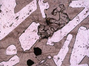
In igneous rocks, mineral shape helps us determine the crystallization order from the magma and allows us to connect observations in thin section to thermodynamic models.
Guided Inquiry
Cleavage and Fracture
Cleavage and fracture can be used to help distinguish minerals in thin section.
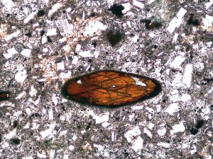
Cleavage is the tendency of minerals to break along atomic planes of weakness within the crystal structure. Minerals may have one or more directions of cleavage dictated by the atomic arrangement and bonding within that mineral.
Muscovite is an example of a mineral with 1 direction of perfectly defined cleavage: https://skfb.ly/6SYYB
Whereas plagioclase has three unique directions of cleavage: https://skfb.ly/6FYU6
Fractures are irregular cracks within a mineral. These can form within any mineral, but when only fractures appear in a mineral, it may indicate that it has poor or no cleavage.
Guided Inquiry
References
Figure 2.6.1. Earth Optics Video 1: Plane Polarized Light. Earth Optics Videos, Creative Commons Attribution License. https://youtu.be/ahS5KlXqQXc
Media Attributions
- Figure2_6_4 92GarnetPyroxenePPL © Elizabeth Johnson is licensed under a CC BY-SA (Attribution ShareAlike) license
- 2_6_5 Glaucophane ppl 0deg 2_5x © Elizabeth Johnson is licensed under a CC BY-NC-SA (Attribution NonCommercial ShareAlike) license
- Forsterite_on_Sanidine_-_Ochtendung,_Eifel,_Germany © Fred Kruijen is licensed under a CC BY-SA (Attribution ShareAlike) license
- Olivine-gem7-10a © Rob Lavinsky, iRocks.com is licensed under a CC BY-SA (Attribution ShareAlike) license
- Fayalite_crystal_group_-_Ochtendung,_Eifel,_Germany © Ra'ike is licensed under a CC BY-SA (Attribution ShareAlike) license
- 2_6_11BC31OlivinePPL © Elizabeth Johnson is licensed under a CC BY-NC-SA (Attribution NonCommercial ShareAlike) license
- 27HornblendePPLEdited © Elizabeth Johnson and Mark Peale is licensed under a CC BY-NC-SA (Attribution NonCommercial ShareAlike) license

