3.5 Polarization of Light
Polarized Light
Polaroid sunglasses are familiar to most of us. They have a special ability to cut the glare of light reflected from water or glass. Polaroids have this ability because of a wave characteristic of light called polarization. What is polarization? How is it produced? What are some of its uses? The answers to these questions are related to the wave character of light.
Watch the first 6 minutes of the video below to see a practical overview of plane polarized light, using crossed polarizers, and how a third polarizer (which is how many minerals act) can be used to increase light output from crossed polarizers.
Electromagnetic waves are transverse waves consisting of varying electric and magnetic fields that oscillate perpendicular to the direction of propagation and perpendicular to each other.
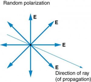
The Sun and many other light sources produce waves in which E (and B, though it is not shown) are not preferentially oriented – they exist in every direction perpendicular to the direction of propagation (see Figure 2.3.11). Such light is said to be unpolarized because it is composed of many waves with all possible directions of polarization.
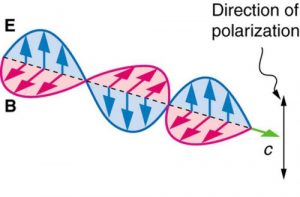
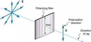
In contrast, light that is plane polarized (also called linearly polarized) has E oriented in one specific direction in space (Figure 2.3.12). The polarization direction is defined by the orientation of E (as opposed to B).
Polarizers are composed of long molecules aligned in one direction. Thinking of the molecules as many slits, analogous to those for the oscillating ropes, we can understand why only light with a specific polarization can get through. The axis of a polarizing filter is the direction along which the filter passes the electric field of an EM wave (see Figure 2.3.13).
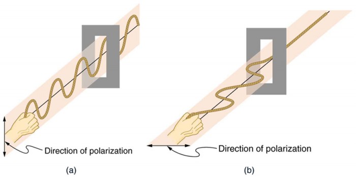
To examine this further, consider the transverse waves in the ropes shown in Figure 2.3.13. The oscillations in one rope are in a vertical plane and are said to be vertically polarized. Those in the other rope are in a horizontal plane and are horizontally polarized. If a vertical slit is placed on the first rope, the waves pass through. However, a vertical slit blocks the horizontally polarized waves. For EM waves, the direction of the electric field vector E is analogous to the disturbances on the ropes (Figure 2.3.14).
ATOMIC EXPLANATION OF POLARIZING FILTERS
Polarizing filters have a polarization axis that acts as a slit. This slit passes electromagnetic waves (often visible light) that have an electric field parallel to the axis. This is accomplished with long molecules aligned perpendicular to the axis as shown in Figure 2.3.15.
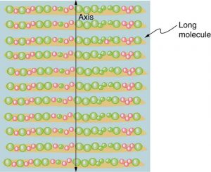
Figure 2.3.16 illustrates how the component of the electric field parallel to the long molecules is absorbed. An electromagnetic wave is composed of oscillating electric and magnetic fields. The electric field is strong compared with the magnetic field and is more effective in exerting force on charges in the molecules. The most affected charged particles are the electrons in the molecules, since electron masses are small. If the electron is forced to oscillate, it can absorb energy from the EM wave. This reduces the fields in the wave and, hence, reduces its intensity. In long molecules, electrons can more easily oscillate parallel to the molecule than in the perpendicular direction. The electrons are bound to the molecule and are more restricted in their movement perpendicular to the molecule. Thus, the electrons can absorb EM waves that have a component of their electric field parallel to the molecule. The electrons are much less responsive to electric fields perpendicular to the molecule and will allow those fields to pass. Thus the axis of the polarizing filter is perpendicular to the length of the molecule.
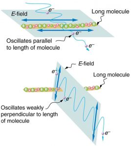
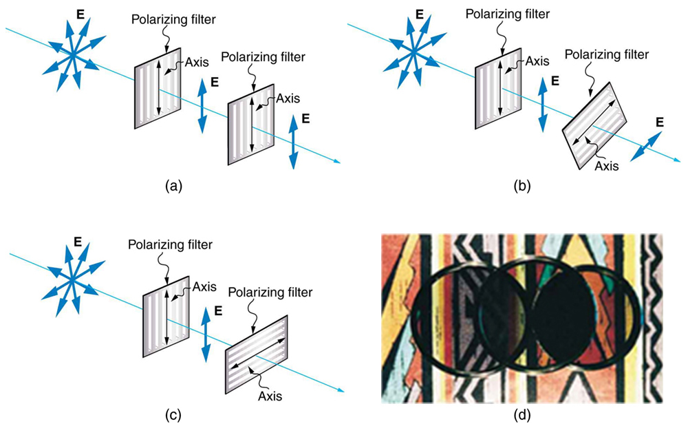
Figure 2.3.17 shows the effect of two polarizing filters on originally unpolarized light. The first filter polarizes the light along its axis. When the axes of the first and second filters are aligned (parallel), then all of the polarized light passed by the first filter is also passed by the second. If the second polarizing filter is rotated, only the component of the light parallel to the second filter’s axis is passed. When the axes are perpendicular, no light is passed by the second.
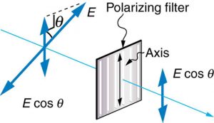
Only the component of the EM wave parallel to the axis of a filter is passed. Let us call the angle between the direction of polarization and the axis of a filter θ. If the electric field has an amplitude E, then the transmitted part of the wave has an amplitude E cos θ (see Figure 2.3.18). Since the intensity of a wave is proportional to its amplitude squared, the intensity I of the transmitted wave is related to the incident wave by I = I0 cos2 θ, where I0 is the intensity of the polarized wave before passing through the filter.
Liquid Crystal DISPLAYS and Optically Active Materials
While you are undoubtedly aware of liquid crystal displays (LCDs) found in watches, calculators, computer screens, cellphones, flat screen televisions, and other myriad places, you may not be aware that they are based on polarization. Liquid crystals are so named because their molecules can be aligned even though they are in a liquid. Liquid crystals have the property that they can rotate the polarization of light passing through them by 90 degrees. Furthermore, this property can be turned off by the application of a voltage, as illustrated in Figure 2.3.19. It is possible to manipulate this characteristic quickly and in small well-defined regions to create the contrast patterns we see in so many LCD devices.
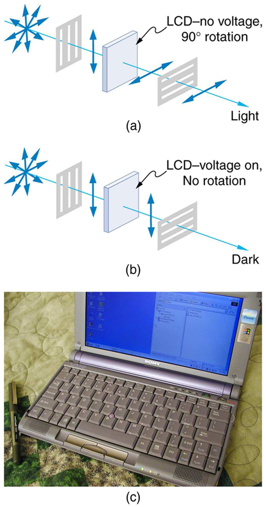
In flat screen LCD televisions, there is a large light at the back of the TV. The light travels to the front screen through millions of tiny units called pixels (picture elements). One of these is shown in Figure 2.3.19 (a) and (b). Each unit has three cells, with red, blue, or green filters, each controlled independently. When the voltage across a liquid crystal is switched off, the liquid crystal passes the light through the particular filter. One can vary the picture contrast by varying the strength of the voltage applied to the liquid crystal.
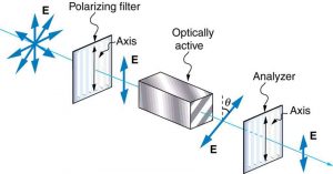
Many crystals and solutions rotate the plane of polarization of light passing through them. Such substances are said to be optically active. Examples include sugar water, insulin, and collagen (see Figure 2.3.20). In addition to depending on the type of substance, the amount and direction of rotation depends on a number of factors. Among these is the concentration of the substance, the distance the light travels through it, and the wavelength of light. Optical activity is due to the asymmetric shape of molecules in the substance, such as being helical. Measurements of the rotation of polarized light passing through substances can thus be used to measure concentrations, a standard technique for sugars. It can also give information on the shapes of molecules, such as proteins, and factors that affect their shapes, such as temperature and pH.
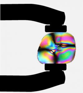
Glass and plastic become optically active when stressed; the greater the stress, the greater the effect. Optical stress analysis on complicated shapes can be performed by making plastic models of them and observing them through crossed filters, as seen in Figure 2.3.21. It is apparent that the effect depends on wavelength as well as stress. The wavelength dependence is sometimes also used for artistic purposes.
Birefrigence
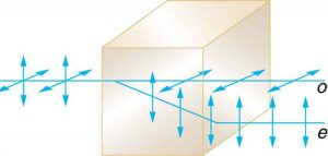
Another interesting phenomenon associated with polarized light is the ability of some minerals and other crystals to split an unpolarized beam of light into two polarized beams (Figure 2.3.22). Such crystals are said to be birefringent.
Each of the separated rays has a specific polarization. One behaves normally and is called the ordinary ray (o or ω), whereas the other does not obey Snell’s law and is called the extraordinary ray (e or ε). Birefringent crystals can be used to produce polarized beams from unpolarized light. Some birefringent materials preferentially absorb one of the polarizations. These materials are called dichroic and can produce polarization by this preferential absorption. This is fundamentally how polarizing filters and other polarizers work. We will use the property of birefringence to help us identify and distinguish minerals in thin section!