16 Assemblies
Frances Davis and Wally Baumback
Learning Outcomes
When you have completed this module, you will be able to:
- Create an assembly by mating parts.
- Create a presentation file to generate an exploded view of the assembly.
- Create an assembly drawing including a parts list.
Jump to section links
Assemblies
An assembly file contains the information required to assemble two or more part files to create an assembled model. As the model is assembled, assembly constraints must be assigned so that each part knows how it aligns or fits with the other parts in the assembled model. A part (.ipt) file that has been placed in the assembly can be edited while in the assembly file and the modifications will be saved back to the original part file. On the other hand, if the original part file is modified after the assembly file has being created, the modifications will automatically display in the assembly. Keep in mind when sending files that an Inventor assembly file does not actually contain any of the part files that are placed in the file, it simply contains a reference to them. As a result, the assembly file and the individual parts files must be sent together.
Creating an Assembly File

To create an assembly file, use the NEW command and select an assembly template rather than a part template. An assembly file has the extension .iam.
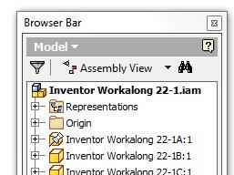
When an assembly is the active file, the Browser bar will display all of the parts that have been placed in the assembly. If the same part is placed more then once into the assembly file, the Browser bar will number them accordingly. For example, this may happen if an assembly required two identical bolts. Only one part file is created and named Bolt.ipt. It is then placed into the assembly file twice. The Browser bar would number the bolts parts as follows:
On the first occurrence: Bolt:1
On the second occurrence: Bolt:2
Assembly Constraints
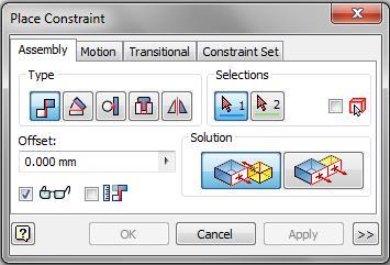
There are many different methods for applying constraints used when creating an assembly. In this module, only the constraint panel will be taught (dialog box shown below). A mate constraint constrains two assembled parts to one another by mating their centerlines and/or by mating a face on one part to a face on the other part. The angle constraint allows to fix the angle between to lines or surfaces. The tangent constraint allows to force a circular surface and plane to be tangent. The insert constraint is used to match the centerline of two circular objects. The symmetric constraint enforces a plane of symmetry.
Mating is the most common way to assemble two parts together. However it often takes more than one mate to assemble two parts together.
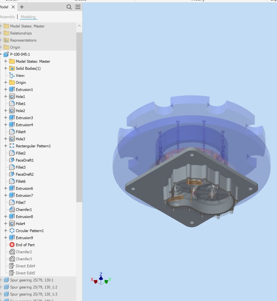
Editing Parts
While working in an assembly you can edit a part within the assembly by double clicking on that part within the model tree. The model tree will now display the model tree for the part with the remaining parts in the assembly greyed out. The remaining components in the assembly will also become semi-transparent in the main screen. You will be able to edit the part as you would from the part file.
Presentation Files
 After the model is assembled in the assembly file, a presentation file can be created. A presentation file is a file in which a view of an assembly is exploded and can be animated. It can also be rotated so that the assembly can be viewed from different angles. A presentation file is created using the NEW command and selecting a presentation template. A presentation file has the extension .ipn.
Exploded Views
An exploded view shows the assembly as if it were dismantled and the components of the assembly shown in the order and orientation that they fit together to create the assembly.
Assemblies can be exploded by tweaking manually. A tweak is the distance that the part is moved from the grounded part while the lines in an exploded view that show path the part traveled from its initial position. Combined, they indicate the direction and distance that a component was moved to create the view. Exploded assembly drawings are used in design presentations, catalogues, and assembly instruction.
Tweaking
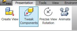
Tweaking is the process of moving the components from the grounded component. The tweak is the distance measured from the grounded unit. To tweak components manually, use the TWEAK COMPONENT command.
Animations

After the exploded assembly is tweaked, it can animated to show the assembly and the disassembly of the model. An animation is simply a series of frames or pictures of the assembly displayed one frame at a time. The amount of time between frames is called the interval. The larger the interval, the slower the animation and the shorter the interval, the faster the animation. The number of repetitions can also be set. The end result is a short movie of the assembly or a disassembly.
Assembly Drawings
Assembly drawings generally include an exploded view of the assembly along with an isometric view. To take the exploded view from the presentation file to the drawing file you will need to take a snapshot of the exploded view. You can then use the snapshot to create an exploded view of the assembly in the drawing file.
Workalong
This workalong involves:
- applying multiple assembly mates
- editing parts in an assembly
| Piston Cylinder Assembly | Time Allowed: 80 min. | |
| Part Name: PistonCylinderAssembly | Project: | Units: in |
| Template: Standard (in).iam |
Color: By part | Material: By part |
|
This assembly includes five (5) parts, Piston Case, Piston, Wrist Pin, Connecting Rod, and Crankshaft. Each part was created earlier as either as a workalong or as an exercise. This workalong starts assuming that you have built all of the parts before starting. The work is broken up into two videos: applying the mates to create the assembly and using the assembly to make an exploded view of the assembly and create a drawing file. |
||
Assembly Video
|
||
Assembly Drawing Video
|
||
Exercises
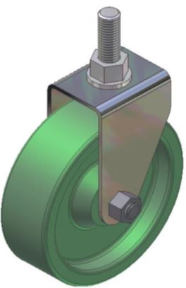
| Caster Assembly | Time Allowed: 180 min. | |
| Part Name: CasterAssembly | Project: | Units: Millimeters |
| Template: Standard (mm).iam |
Color: By part | Material: By part |
|
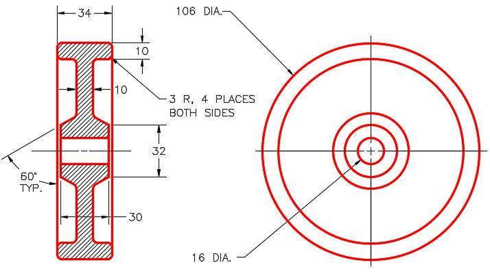
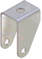
This assembly includes eight (8) parts, labeled A – H. The material and appearance is given for each part. Draw the necessary sketches and extrude or revolve them to produce the each of the solid models shown below. Apply all of the necessary geometrical and dimensional constraints to maintain the objects shape and size. Create all fillets after each solid model is totally constructed. Once all eight parts are created assemble them to create the model shown below. The frame (Part B) should be grounded in the assembly. The bushing fits in the wheel. The wheel and the washer should be free to rotate.
|
||
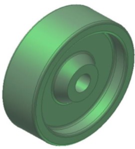
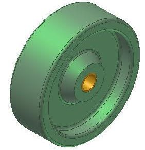
Part A – Wheel |
||
| Template: Standard (mm).ipt |
Color: Olive Green | Material: Rubber |
  |
||
Part B – Frame |
||
| Template: Standard (mm).ipt |
Color: Aluminum Polished | Material: Steel |
|
||
Part C – Bushing |
||
| Template: Standard (mm).ipt |
Color: Brass Satin | Material: Brass, Soft Yellow |
  |
||
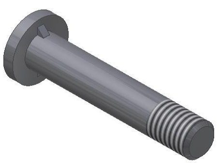
Part D – Pin |
||
| Template: Standard (mm).ipt |
Color: Semi-Polished | Material: Steel |
|
||
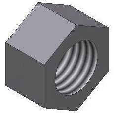
Part E – 10 mm Nut |
||
| Template: Standard (mm).ipt |
Color: Semi-Polished | Material: Steel |
  |
||
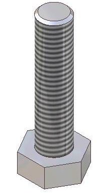
Part F – Bolt |
||
| Template: Standard (mm).ipt |
Color: Semi-Polished | Material: Steel |
  |
||
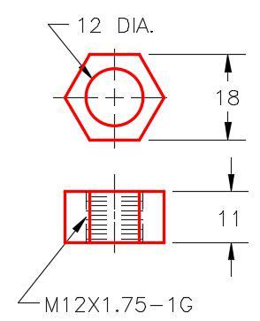
Part G – 12 mm nut |
||
| Template: Standard (mm).ipt |
Color: Semi-Polished | Material: Steel |
  |
||
Part H – Washer |
||
| Template: Standard (mm).ipt |
Color: Cyan | Material: Steel |
 |
||
| Slotted Connector Assembly | Time Allowed: 180 min. | |
| Part Name: SlottedConnector | Project: | Units: Millimeters |
| Template: Standard (mm).iam |
Color: By part | Material: By part |
|
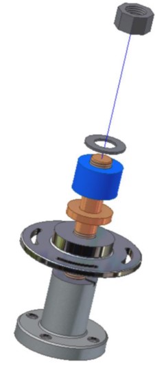
This assembly includes six (6) parts, labeled A – F. The material and appearance is given for each part. Draw the necessary sketches and extrude or revolve them to produce the each of the solid models shown below. Apply all of the necessary geometrical and dimensional constraints to maintain the objects shape and size. Create all fillets after each solid model is totally constructed. Once all six parts are created assemble them to create the model shown below. The base (Part A) should be grounded in the assembly.
|
||
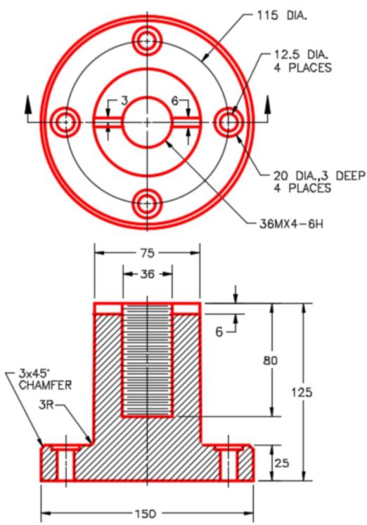
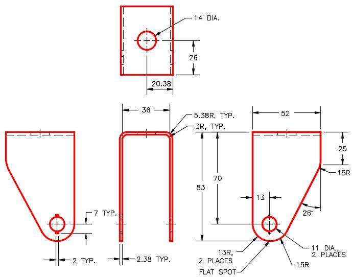
Part A – Base |
||
| Template: Standard (mm).ipt |
Color: Aluminum Cast | Material: Aluminum 6061 |

|
||
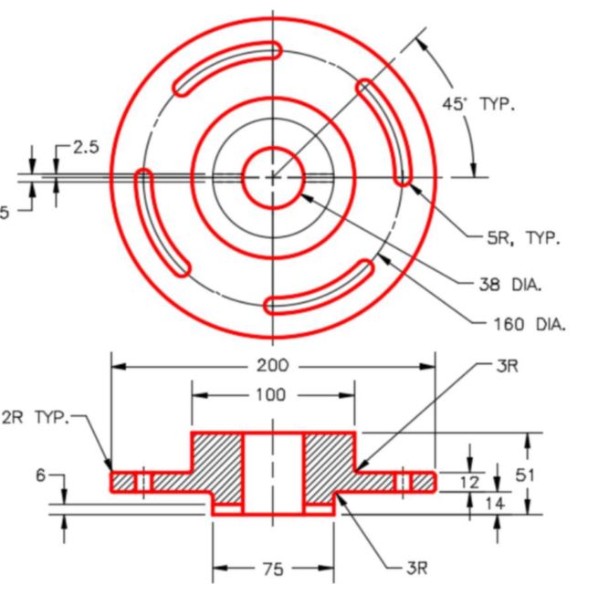
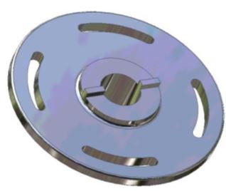
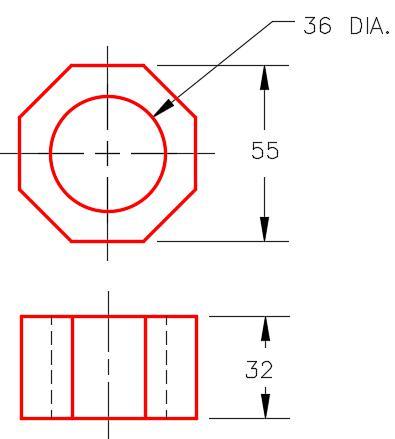
Part B – Slotted Wheel |
||
| Template: Standard (mm).ipt |
Color: Light Steel Blue | Material: Steel |
|
||
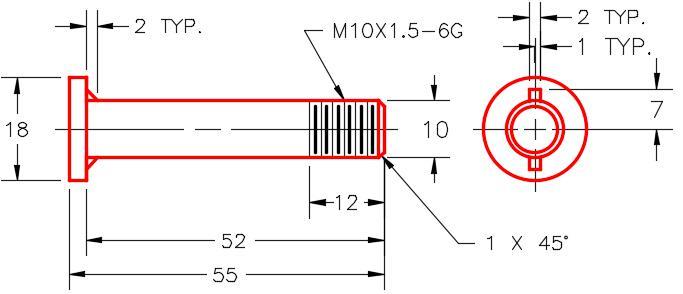
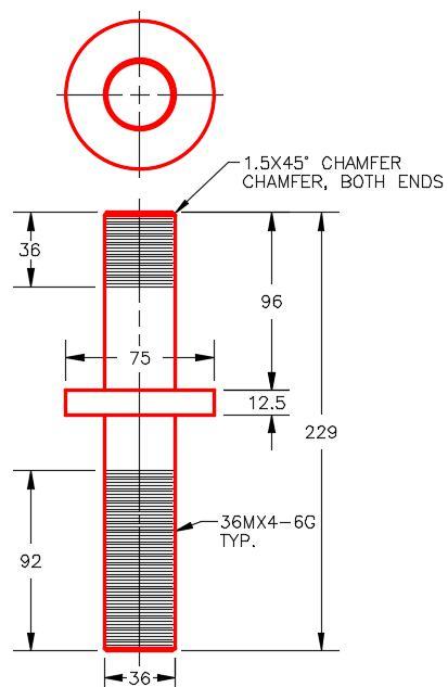
Part C – Connecting Shaft |
||
| Template: Standard (mm).ipt |
Color: Copper Polished | Material: Copper |
  |
||
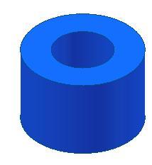
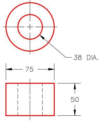
Part D – Spacer |
||
| Template: Standard (mm).ipt |
Color: Blue – Wall Paint – Glossy | Material: ABS Plastic |
|
||
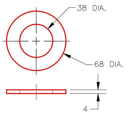
Part E – Washer |
||
| Template: Standard (mm).ipt |
Color: Semi-Polished | Material: Steel |
  |
||
Part F – Nut |
||
| Template: Standard (mm).ipt |
Color: Semi-Polished | Material: Steel |
  |
||