11 Extrude
Frances Davis and Wally Baumback
Learning Outcomes
When you have completed this module, you will be able to:
- Use basic Inventor commands to draw a sketch.
- Use extrude to add material to a part.
- Use extrude to remove material from a part.
Jump to section links:
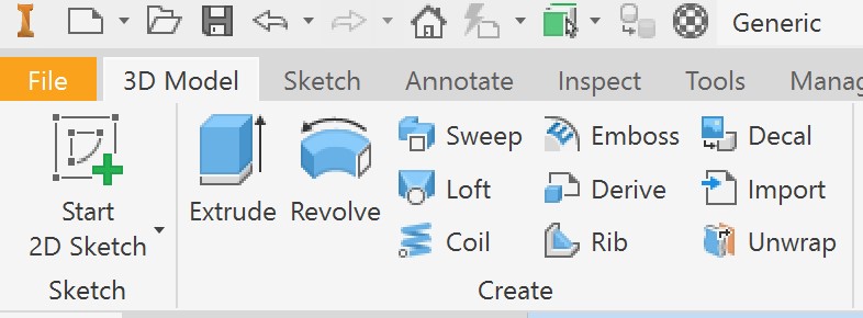
Inventor Commands
Inventor Commands
An Inventor command is an instruction from you to Inventor instructing it what operation to perform. Commands can be entered by selecting an item from a Pull-down menu, a Right-click menu, an icon on a Toolbar, an item on the Panel menu, or entering a shortcut on the keyboard. Similar to the Navigation controls discussed in the previous chapter, there are usually many different ways of entering the same command, you should select the method that works the best for you.
Ending the Current Command
When you enter a command, Inventor must be instructed to end the current command. There are two methods available to do this. The first is to press the Esc key on the keyboard and the second is click to Done or Cancel on the Right-click menu.
Creating Sketches
The base sketch is the first 2D sketch drawn in a new part. Before drawing the base sketch, you should study the model being constructed to determine the best face to start with and the plane to draw it on. The best face to use is the view with the most complex contour shape. The goal when drawing a base sketch to match the scale and shape of the model. Adding dimensions later will make the sketch the appropriate size. However, when the dimensions are known for a part it can be useful to input the values as you are creating the sketch.
Rules for a strong base sketch
- The objects in the sketch must meet exactly at their endpoints and cannot overlap.
- The objects must form a perfect closed polygon and cannot contain any gaps.
- Geometric constraints should be applied to control the shape of the sketch.
- Leave fillets and chamfers out of the original sketch. They can be added to the model after it is created.
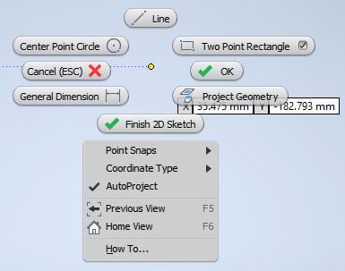
Right-Click Menu
When the right mouse button is clicked, it displays the Right-click menu. It is sometimes called the radial menu since it displays a circle of options at the current location of the cursor. This menu changes automatically depending on the current command or operation being performed. This menu is often convenient to use while sketching.
Constraints
Geometric constraints are used to apply/enforce relationships between 2D objects in a sketch. By applying geometric constraints, the number of dimensional constraints required to fully constrain the model is reduced. Applying the correct geometric constraints prevents unwanted changes to a feature when geometry or dimensions are modified. Commonly applied relationships include horizontal, vertical, parallel, or perpendicular.
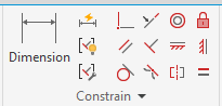
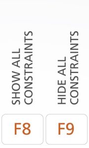
Some geometric constraints are automatically applied as the sketch is drawn, you will the lines in the sketch snap and the matching icon for the constraint appear in the sketch. Constraints can also be added after you finish drawing. If you float your cursor over the icon it will describe what each constraint does. To see all of the constraints in a sketch you can use the function keys F8 and F9 to show and hid the constraints respectively.
A list of selected geometric constraints is given below.
|
Selected Geometric Constraints |
||
|
Constraint |
Icon |
Definition |
|
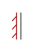
Vertical |
|
A vertical constraint is applied to a line that lies on or is parallel to the Y axis of the coordinate system. |
|
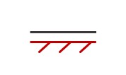
Horizontal |
|
A horizontal constraint is applied to a line that lies on or is parallel to the X axis of the coordinate system. |
|
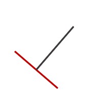
Perpendicular |
|
A perpendicular constraint is applied to two lines that are at right angles to each other. |
|
Parallel |
|
A parallel constraint is applied to two lines that are parallel to each other. |
|
Coincident |
|
A coincident constraint is applied to two points or endpoint of lines that are constrained to same point. |
|
Tangent |
|
A tangent constraint is applied a circular section and a line segment. This makes the slope at the two end points match. |


In a sketch, dimensional constraints control the size (scale) of the geometry. To fully constrain a 2D sketch, dimensional and geometric constraints are required. Inventor will automatically change the colors of lines in a sketch to show that the lines are fully constrained. Inventor will issue a warning when a dimension is added that over-constrains the sketch. Only driven dimensions will be allowed to be added to a fully constrained sketch.
A driven dimension is a non-parametric dimension that does not constrain the object. It only displays the current value of the geometry that it is applied to. Driven dimensions are automatically enclosed in parentheses to distinguish them from driving dimensions.
Inventor Command: GENERAL DIMENSION
The GENERAL DIMENSION command is used to create dimensional constraints on a sketch.
Extrude
The extrusion command takes a 2D sketch and gives it some thickness. The images below show how a 2D sketch is extruded to make a model.
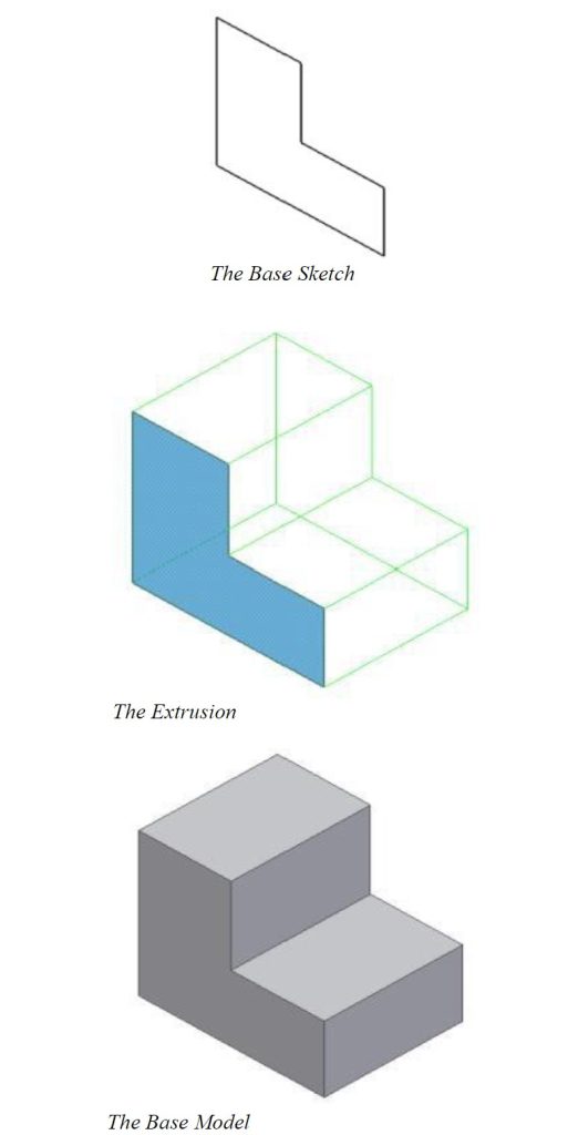
Inventor Command: EXTRUDE
EXTRUDE is used to add thickness to a 2D sketch to form a 3D feature.
Workalong
Extrude Workalong 1
This workalong uses
- extrude to add and remove material from a part
- project geometry
- driven dimensions
| Extrude Workalong 1 | ||
| Part Name: Inventor_ExtrudeWorkalong1 | Project: | Units: Inches |
| Template: Standard (in).ipt | Color: Slate Blue | Material: Titanium |
|
Step 1 Start a new part file with the template and filename shown above. Step 2 Follow along with the video to create the part shown below.
|
||
Workalong 2
This workalong uses
- extrude to add and remove material from a part
- the hole tool to create a counterbored hole
- project geometry
- 3D fillet
| Extrude Workalong 2 | ||
| Part Name: Inventor_ExtrudeWorkalong2 | Project: | Units: Inches |
| Template: Standard (in).ipt | Color: N/A | Material: N/A |
|
Step 1 Start a new part file with the template and filename shown above. Step 2 Follow along with the video to create the part shown below.
|
||
Workalong 3
This workalong uses
- extrude to add and remove material from a part
- center point circle
- center point arc
- construction lines
- offset
| Extrude Workalong 3 | ||
| Part Name: Inventor_ExtrudeWorkalong3 | Project: | Units: mm |
| Template: Standard (mm).ipt | Color: Set by material | Material: Stainless Steel |
|
Step 1 Start a new part file with the template and filename shown above. Step 2 Follow along with the video to create the part shown below.
|
||
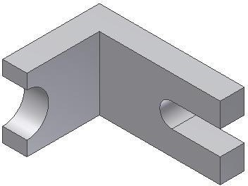

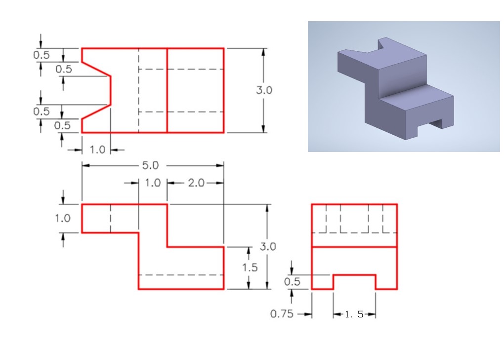
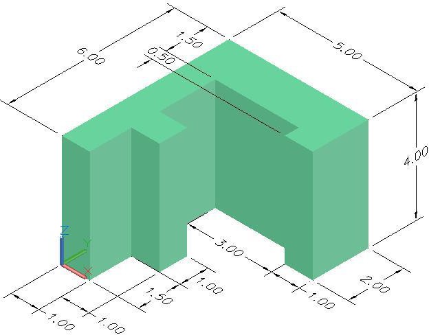
Exercises
| Practice Exercise 2- 1 | Time Allowed: 40 Min. | |
| Part Name: Inventor_Ch2E01 | Project: | Units: Inches |
| Template: Standard (in).ipt | Color: Aluminum – Flat | Material: N/A |
|
Step 1 Start a new part file with the template and filename shown above. Step 2 Draw the Base sketch for the object shown in the figure and apply all of the necessary geometric constraints to maintain the shape of the sketch. Step 3 Insert the necessary dimensions to fully constrain the sketch. Add at least 1 driven dimension. Step 4 Extrude the part to appropriate thickness.
|
||
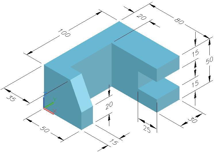
| Practice Exercise 2- 2 | Time Allowed: 45 Min | |
| Part Name: Inventor_Ch2E02 | Project: Inventor Course | Units: Millimeters |
| Template: Standard (mm).ipt | Color: Steel | Material: N/A |
|
Step 1 Start a new part file with the template and filename shown above. Step 2 Draw the necessary sketches and extrude them to produce the solid model. Apply all of the necessary geometric and dimensional constraints to fully constrain all sketches Step 3 Apply the color shown above.
|
||
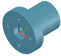
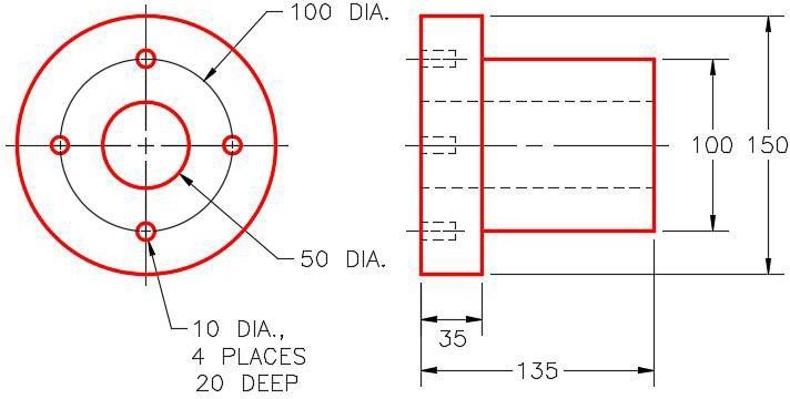
| Practice Exercise 2- 3 | Time Allowed: 45 Min. | |
| Part Name: Inventor_Ch2E03 | Project: Inventor Course | Units: Millimeter |
| Template: Standard (mm).ipt | Color: Aluminum – Flat | Material: N/A |
|
Step 1 Start a new part file with the template and filename shown above. Step 2 Draw the necessary sketches and extrude them to produce the solid model shown below. Apply all of the necessary geometric and dimensional constraints to fully constrain all sketches. Step 3 Apply the color shown above. Hint: The small holes do NOT go all the way through the flange.
|
||