15 Drawings
Frances Davis and Wally Baumback
Learning Outcomes
When you have completed this module, you will be able to:
- Read a drawing file and use it to create a part file.
- Build a drawing file in Inventor.
- Dimension a drawing file in Inventor.
- Include special views such as section and auxiliary views in a drawing file.
Jump to section links
Projections and the Glass Box
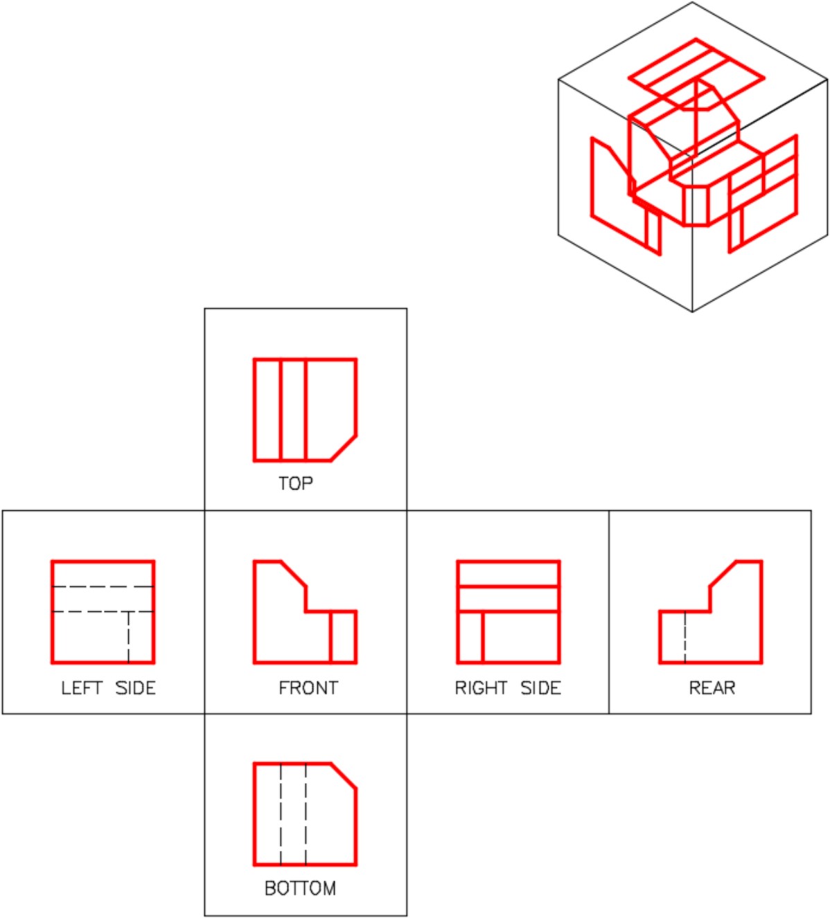
Imagine placing a plane on each side of the object shown below for a total of six planes or sheets of glass to form a glass box. Picture unfolding the glass box onto a flat two-dimensional plane. All six views are now visible at the same time and a three-dimensional object can be pictured using two dimensional projections.

Isometric View & Standard Drawing Views
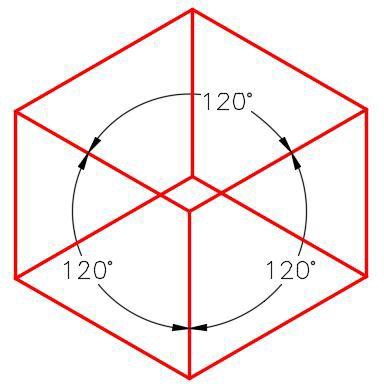
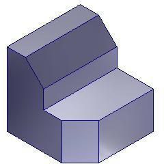
An isometric drawing is a 2-dimensional drawing that has the XYZ axis drawn 120 degrees apart as shown in below. An isometric drawing allows you to sketch the depth of an object.
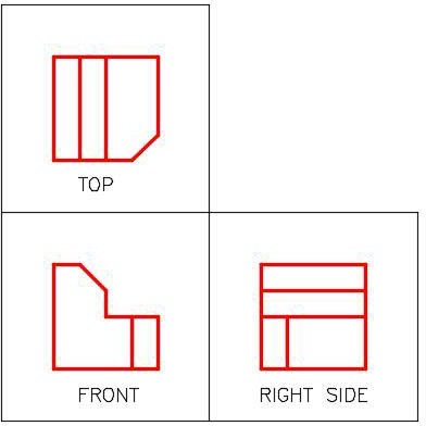
The glass box projections produced six views: Top, Front, Right Side, Left Side, Rear, and Bottom. In almost all objects, three views standard drawing views are adequate to describe it. The three standard views are the Top, Front, and Right Side. They retain the positions shown below from the glass box projection. In addition, all of the views are aligned. While three views are standard, keep in mind that there are many objects that only need two views and some that only need one view to describe it.
Drawing Files
A drawing file contains one or more drawing sheets on which 2 dimensional and/or 3 dimensional scaled views of the solid models contained in part, assembly, or presentation files. A drawing file has the file extension .idw. IDW is an acronym for Inventor DraWing. Annotations can be automatically or manually added to the views as required. Dimensioning, inserting text, and filling in the title block are taught in the workalongs. When the drawing is complete, it can be printed on paper or exported as a pdf.
Drawing Sheets
A drawing sheet represents a blank piece of paper complete with title block and border. The size of drawing sheet can be set by the user. The sheet size can be a custom size set by you or one of the ANSI or ISO drawing sheet standards.
Model Views
A model view is a scaled view orientated at an angle and direction that the solid model or assembly is being viewed and displayed on the drawing sheet. There is no limit to the number of views or the number of solid models from part, assembly, or presentation files that can be placed on a drawing sheet. Views can also be automatically annotated or labeled. There are eight predefined views that you can select from when creating the view. The predefined views are the base, projection, auxiliary, section, detail, broken, breakout, and overlay. In this section we will only cover base, projection, auxiliary, section and detail views.
The Base View
A Base view is the first view created on the drawing sheet. It controls the scale, orientation, and location of the views projected from it. The orthographic and/or isometric views in the drawing are created from the Base view. For example, if a multiview drawing was being created from a solid model, the Front view is created first as a Base view. The Front view would control the scale and location of the projected Top and Right Side views. To change the scale of all views, only the scale of the Front (Base) view would have to be changed and the Top and Right Side views would automatically change scale to match. If the Front view was moved, the Top and Right Side views would move accordingly to keep their multiview position.
A Projected View
A projected view is a view projected from a Base view. The scale of a projected view cannot be set since the Base view that you projected it from controls its scale. The Base view also controls the orientation and location of the projected views.
Styles within a Drawing Sheet
Line Types
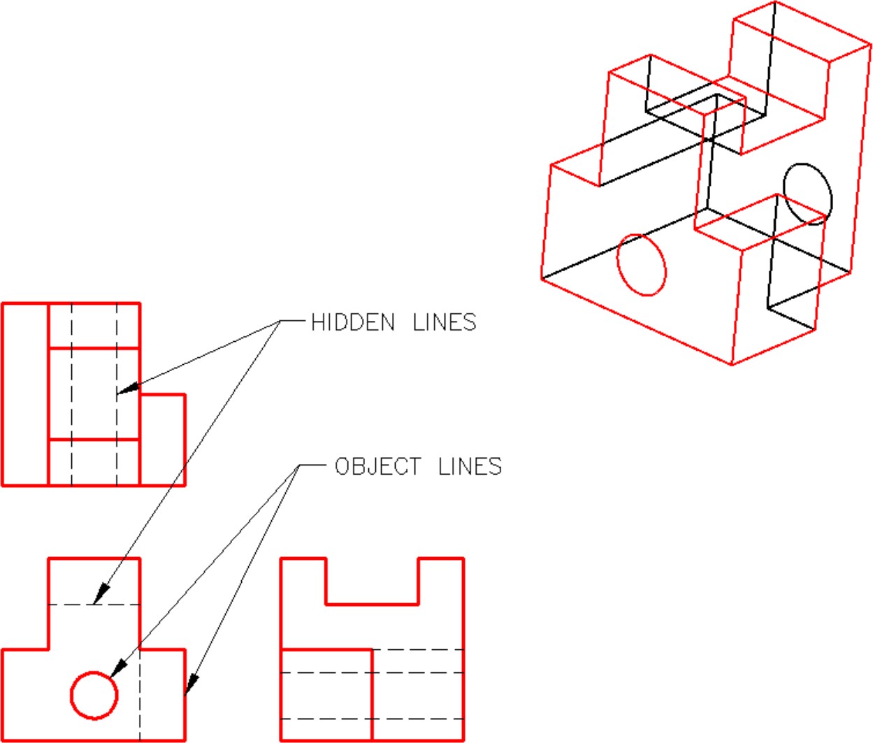
Lines and features that can be seen in the views are drawn with solid lines called object lines. To completely describe an object in a multiview drawing, the drafter must also show all lines or features that are hidden in that view. To represent hidden features dashed lines called hidden lines are used. Study the multiview drawing below and take note how the holes going through the object are shown with hidden lines.
View Style
A drawing view can be displayed in one of three different view styles. The three styles are hidden line, hidden line removed, and shaded as shown below. The style of a view can be changed as required after the view has been placed. In general the isometric views of the part or assembly are shaded while the standard views use a hidden line style.
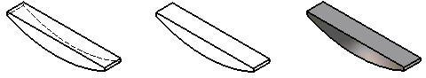
| Hidden Lines | Hidden Lines Removed | Shaded |
View Scale
The scale of the view is a factor of the number that it is set to. For example, if the scale is set to 1 then the factor of 1 X 1 = 1, full scale or 1:1. If the scale is set to 2 then 2 X 1 = 2 or a scale of 2:1 which is twice the size of the original model. On the other hand, if the scale factor is set to 0.5 then 0.5 X 1 = 0.5 or the scale of 1:2 which would display the view one-half the size of the original model. Adjust the scale of the model as needed to fit on the size sheet you have selected.
Centerlines and Center Marks
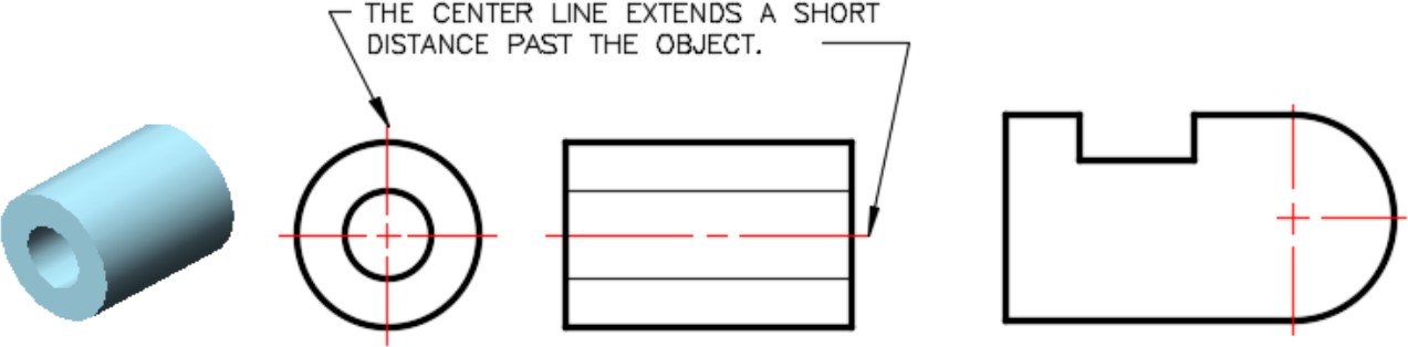
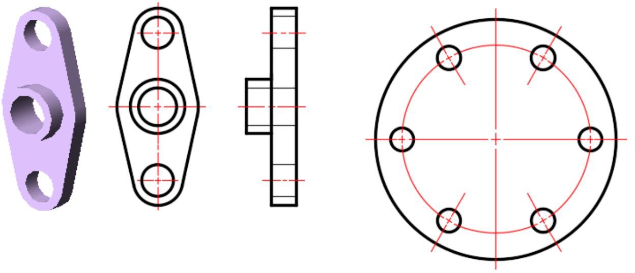
In multiview drawings, the centerline is used to indicate the location of the axis of symmetry. Placing center lines on all objects that have a symmetrical shape will help the reader and save the you from inserting a lot of dimensions. Below are some examples of typical applications of the use of center lines in a multiview drawing.
Dimensioning
Dimensioning is the process of adding size descriptions to model views that are placed on a drawing. Once the views are dimensioned, the drawing sheet can then be plotted and used for construction or reference. Since you have already included the required dimensions when building the part file, you only have to control which dimensions are shown and where to position them. Two types dimensions can be placed on a drawing: model dimensions and drawing dimensions.
Model Dimensions
Model dimensions are the driven and driving dimensions that were placed in the 2D sketch when the model was being constructed. The RETRIEVE DIMENSION command is used to retrieve the dimensions from the model and display them on the drawing. If the dimensions in the original sketches (in the part file) are changed in the future, the model dimensions in the drawing will automatically change since the drawing file and part files are linked in Inventor.
Drawing Dimensions
Drawing dimensions are dimensions that are placed in the drawing using the GENERAL DIMENSION command. Occasionally the dimensions used create the three-dimensional part are not the best dimensions for describing the two-dimensional model views. In this case, additional dimensions can be added using the general dimension command.
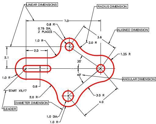
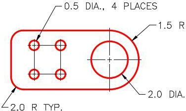
Dimensions for Circles and Arcs
When reading/placing the dimensions for circles and arcs, consider the following:
- Circles are dimensioned as diameters.
- Arcs are dimensioned as radii.
- When there is more than one circle of the same diameter, they are only dimensioned once.
- Sometimes multiple arcs are dimensioned as typical (TYP.). This simply means that there is at least one additional arc of the same size.
Section and Auxiliary Views
Section Views
When a view of an object requires a clearer description of its interior or it is hard to dimension because of the hidden lines, a section view can be drawn in place of the normal multiview.
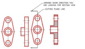
A section view, also called a cross section, is a view of the object as if it were cut along a cutting plane and the two pieces pulled apart exposing the inside of the object. A cutting plane line is the line along the object where the cut would have been made. The arrows point in the direction that you are looking when drawing the section view. The surfaces of the object that are solid, when cut, are crosshatched.
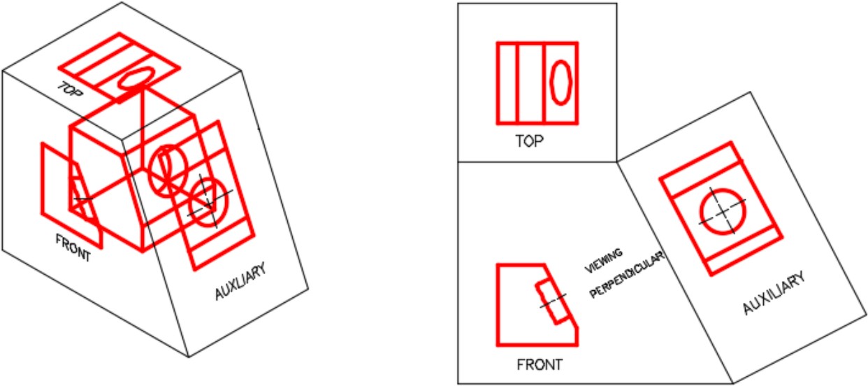
Auxiliary Views
When a model has an inclined side, its plane is not parallel to the horizontal and vertical sides of the glass box. If the inclined view is drawn in one of the predefined views in a multiview drawing, some or all parts of the object will not be their true size and shape. To correct this, an auxiliary view is drawn instead of a predefined view. An auxiliary view is a view looking perpendicular to the inclined plane as shown below.
Workalong
This workalong uses the Extrude Workalong 2 part to build a drawing file.
This workalong show you how to:
- change sheet size
- update the title block
- place base and projected views
- change the view style of a view
- change the scale of a view
- retrieve dimensions from the part file
- use hole and thread feature notes
- add annotations (centerlines and centermarks)
- export file to pdf
| Drawing Workalong | ||
| Part Name: Extrude Workalong 2 | Project: | Units: Inches |
| Template: | Sheet Size: B | Material: N/A |
| The video covers the creation of the drawing file using the part from the Workalong in the Extrude Chapter.
|
||
This workalong uses the Revolve Workalong 2 part to build a drawing file.
This workalong show you how to:
- change sheet size
- update the title block
- place base and projected views
- change the view style of a view
- include a section view
- include a detailed view
- manually dimension a drawing view
- add annotations (centerlines and centermarks)
- add a reference dimension
| Section View Workalong | ||
| Part Name: Revolve Workalong 2 | Project: | Units: in |
| Template: ANSI (in).idw | Sheet Size: B | Material: N/A |
| You will need to build the part first. For directions on building the part, use the Workalong in the Revolve chapter.
|
||
Exercises
| Practice Exercise 5-1 | Time Allowed: 60 Min. | |
| Part Name: Inventor_Ch5E01 | Project: Inventor Course | Units: mm |
| Template: ANSI (mm).idw | Sheet Size: B | Material: N/A |
| You will need to build the part first. Then create a drawing of the part file. The drawing for this part should include an auxiliary view.
|
||
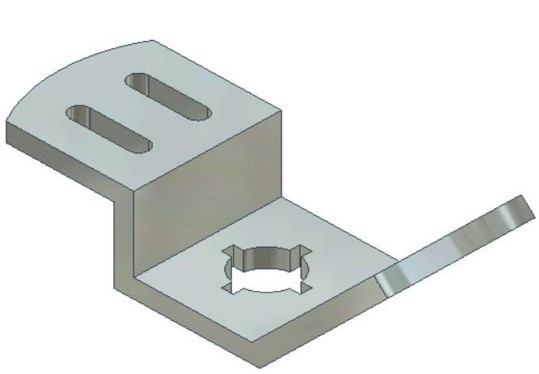
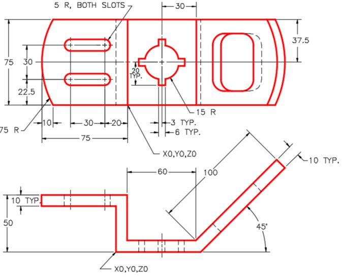
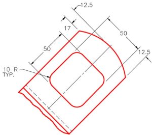
| Practice Exercise 5-2 | Time Allowed: 60 Min. | |
| Part Name: Inventor_Ch5E02 | Project: Inventor Course | Units: mm |
| Template: ANSI (mm).idw | Sheet Size: B | Material: N/A |
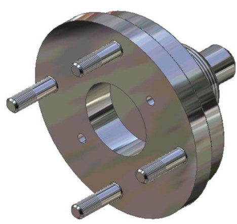
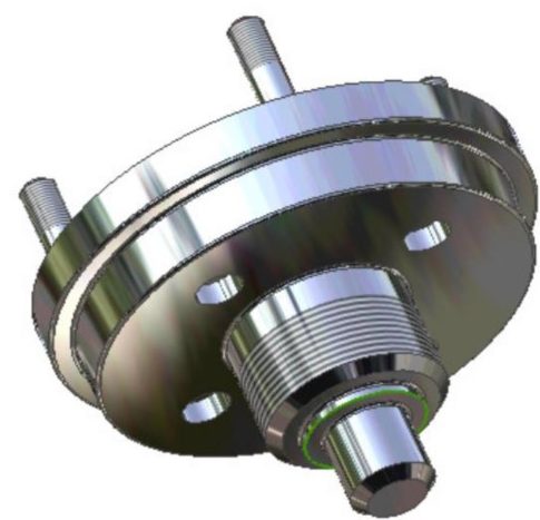
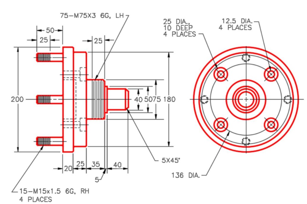
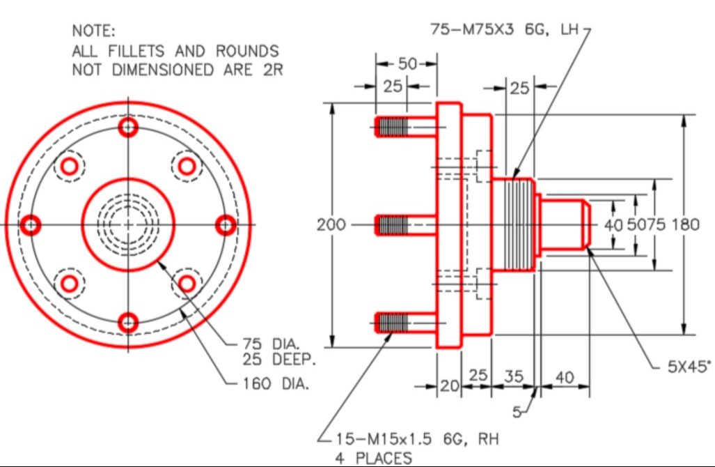
| You will need to build the part first. Then create a drawing of the part file. This drawing requires a section view. Note that both sets of drawings are needed to show the positioning of the upper holes and the lower posts.
|
||