
27 Tilted Beds and Strike and Dip
Elizabeth Johnson
Strike and Dip
To measure and describe the geometry of geological layers, geologists apply the concepts of strike and dip.
Strike refers to the line formed by the intersection of a horizontal plane and an inclined surface. This line is called a strike line, and the direction the line points in (either direction, as a line points in two opposite directions) is the strike angle.
Dip is the angle between that horizontal plane and the inclined surface (such as a geological contact between tilted layers) measured perpendicular to the strike line down to the inclined surface.
A useful way to think about strike and dip is to look at the roof of a house (Figure 1). A house’s roof has a ridge along the top, and then sides that slope away from the ridge. The ridge is like a strike line, and the angle that the roof tilts is the dip of the roof.
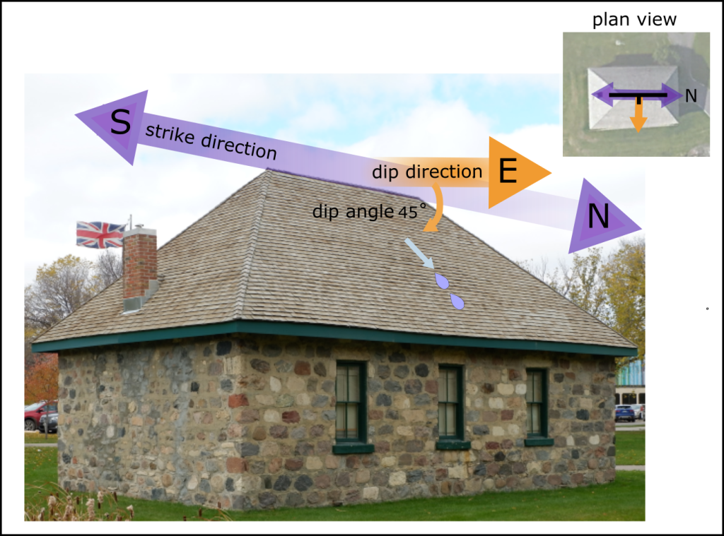
Source: Joyce M. McBeth (2018) CC BY-SA 4.0. Satellite image from © 2018 Google Earth.
Geologists measure the orientation (strike) and steepness (dip angle) of tilted beds of rock at an outcrop (Figure 2). The direction and angle the beds are inclined will vary from location to location, so the location of each outcrop must also be recorded.
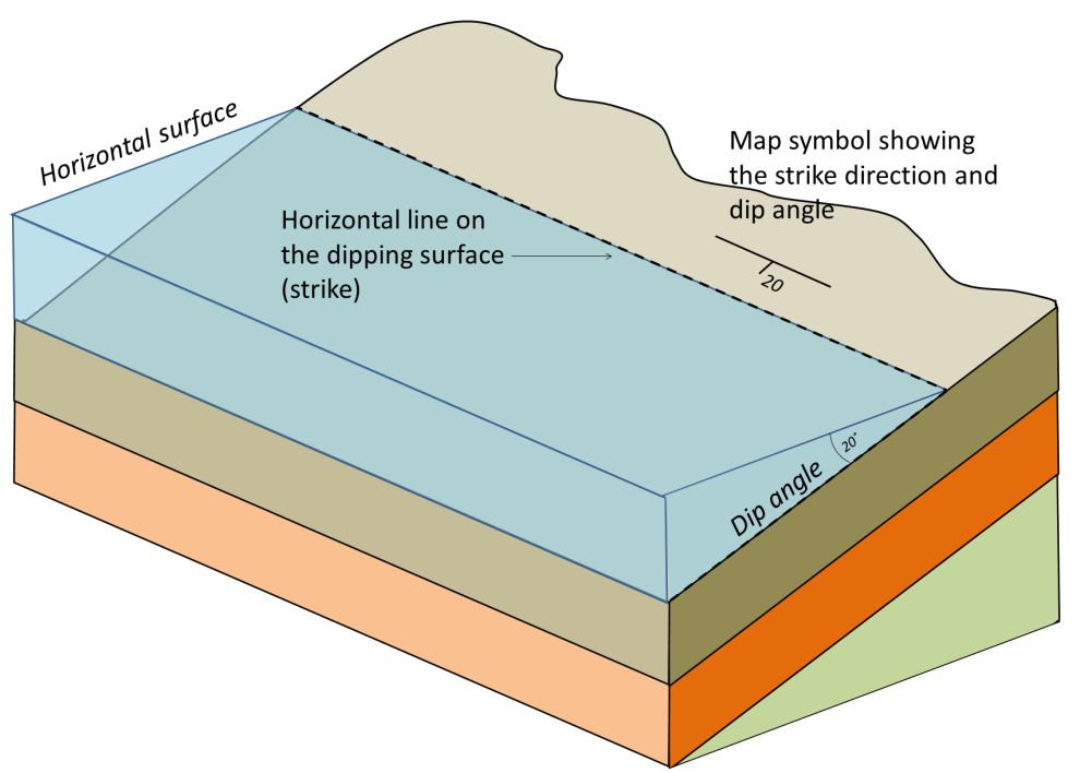
Source: Karla Panchuk (2018) CC BY 4.0. Modified after Steven Earle (2015) CC BY 4.0
On a map, geologists use a strike and dip symbol to represent inclined beds (Figure 3).
Strike and dip map symbols look like the capital letter T, with a short trunk and extra-wide top line. The short trunk represents the dip and the top line represents the strike. Dip is the angle that a bed or layer plunges into the Earth from the horizontal. A number next to the symbol represents dip angle.
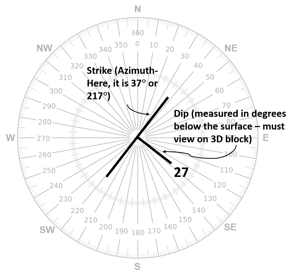
The strike indicates the azimuth (orientation) of the beds on the map – see the section on Azimuth for a description of how this is plotted.
In Figure 3, the strike is measured as either 37 degrees, or 37 + 180 = 217 degrees. Convention is to use the smallest angle (in this case, 37 degrees), but either is correct.
The dip of the inclined layer represents the direction the layer or bed is tilting into the Earth . The direction of dip would be the direction a ball would roll if set on the layer and released. In Figure 3, the layers are dipping to the SE. In this case, the dip is labelled “27 degrees,” so we know it is tilted exactly 27 degrees into the Earth. Sometimes dip angles are not labeled, but we can still determine the dip direction (but not the magnitude) from the dip symbol.
Rules of Strike and Dip
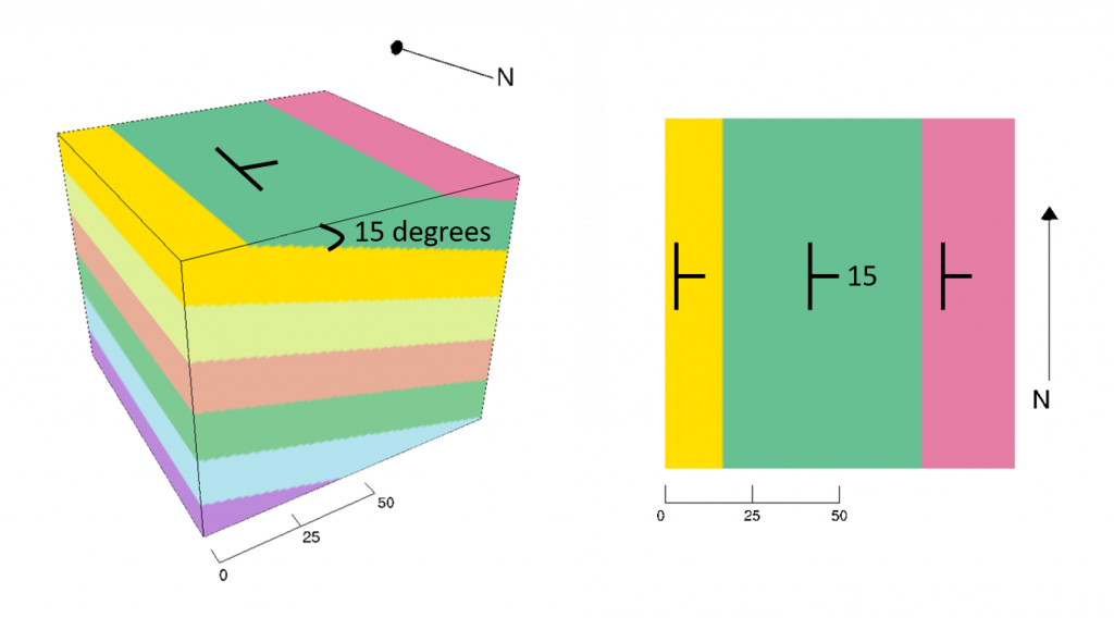
- Strike is always parallel to the bedding direction at that location.
- The dip is always drawn perpendicular to strike in map view. It may be drawn at an angle to show perspective in a 3D block diagram.
- The dip CAN be labelled with the dip angle, or only the direction can be indicated. The dip always shows which way layers are tilting into the Earth.
- Special symbols are used for horizontal beds and vertical beds. A horizontal rock bed has a dip of 0° and a vertical rock bed has a dip of 90°.

Tilted Beds
Tilted beds or layers occur when plate tectonic forces cause horizontal layers to be pushed up or dropped down unevenly. This results in a tilting or incline of the original horizontal beds.
Figure 5. A 3D virtual outcrop of tilted beds (click on link): https://sketchfab.com/3d-models/vom-2-65d74feafc1f4e99a87d0c9d17070fa5
Examples
Here are some examples of tilted beds:
3D interactive model of Figure 6: http://app.visiblegeology.com/model.html#ahFzfnZpc2libGUtZ2VvbG9neXIPCxIFTW9kZWwYqcLLnAEM
3D interactive model of Figure 7: http://app.visiblegeology.com/model.html#ahFzfnZpc2libGUtZ2VvbG9neXIPCxIFTW9kZWwYyeKJpAEM
3D interactive model of Figure 8: http://app.visiblegeology.com/model.html#ahFzfnZpc2libGUtZ2VvbG9neXIPCxIFTW9kZWwYqezDmgEM
Questions
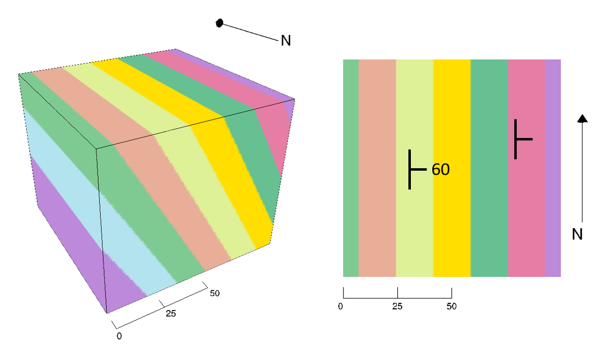
3D interactive model of Figure 9: http://app.visiblegeology.com/model.html#ahFzfnZpc2libGUtZ2VvbG9neXIPCxIFTW9kZWwYyaOkogEM
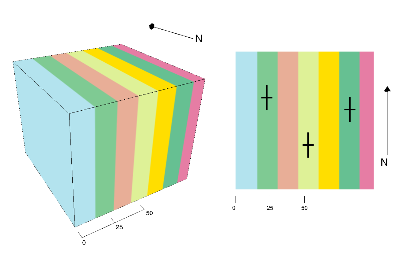
3D interactive model of Figure 10: http://app.visiblegeology.com/model.html#ahFzfnZpc2libGUtZ2VvbG9neXIPCxIFTW9kZWwY-cORowEM
3D interactive model of Figure 11: http://app.visiblegeology.com/model.html#ahFzfnZpc2libGUtZ2VvbG9neXIPCxIFTW9kZWwYibyKoQEM
Some questions, like Questions 5-6, are intentionally left as non-interactive.
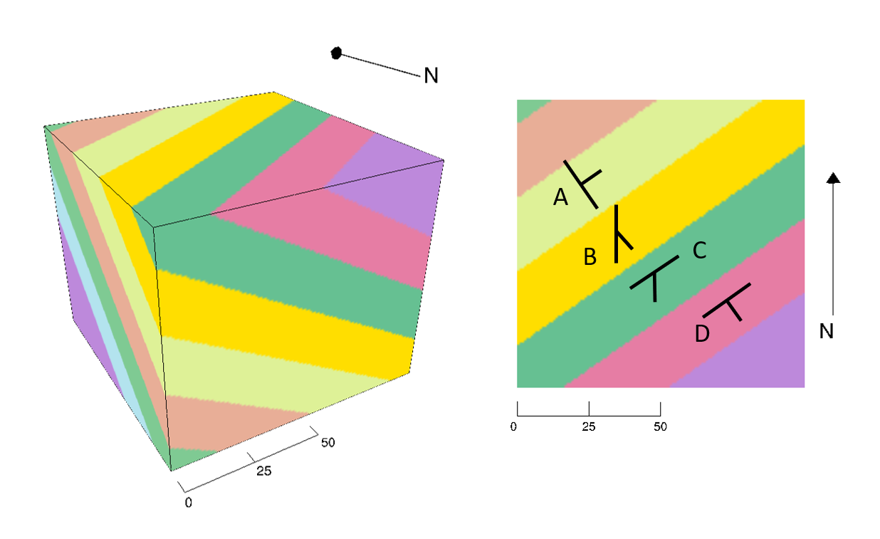
Question 5: Which strike and dip symbol is correct in Figure 11?
- A
- B
- C
- D
3D interactive model of Figure 12: http://app.visiblegeology.com/model.html#ahFzfnZpc2libGUtZ2VvbG9neXIPCxIFTW9kZWwYmp7DmgEM
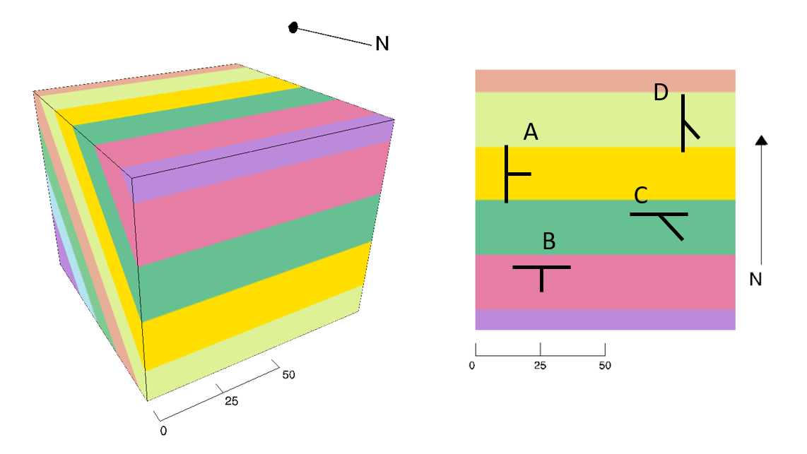
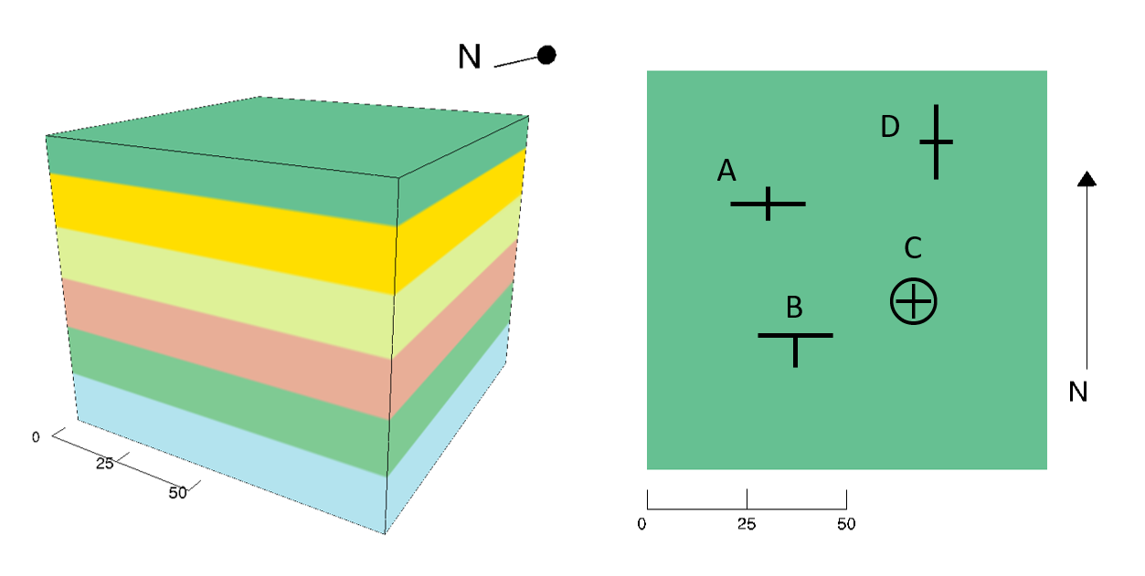
Question 6: Which strike and dip symbol is correct in Figure 12?
- A
- B
- C
- D
References
Text modified from:
- http://opengeology.org/textbook/9-crustal-deformation-and-earthquakes/ CC-BY-SA.
- Adapted by Joyce M. McBeth, Karla Panchuk, Lyndsay R. Hauber, Tim C. Prokopiuk, & Sean W. Lacey (2018) University of Saskatchewan from Deline B, Harris R & Tefend K. (2015) “Laboratory Manual for Introductory Geology”. First Edition. Chapter 12 “Crustal Deformation” by Randa Harris and Bradley Deline, CC BY-SA 4.0. https://openpress.usask.ca/geolmanual/chapter/overview-of-strike-dip-and-structural-cross-sections/
Protractor modified from: https://commons.wikimedia.org/w/index.php?curid=19070259 By Autiwa – Own work, CC BY-SA 3.0, Link
